Bipolar current collector and preparation method thereof

A current collector, bipolar technology, applied in the direction of electrode carrier/current collector, electrolyte battery manufacturing, non-aqueous electrolyte battery, etc. problems, to reduce the influence of the weakening of the electrical conductivity, prevent the short circuit of the battery, and reduce the surface contact resistance.

Active Publication Date: 2015-04-29
BEIJING HAWAGA POWER STORAGE TECH
View PDF4 Cites 31 Cited by
  • Summary
  • Abstract
  • Description
  • Claims
  • Application Information

AI Technical Summary

Problems solved by technology

Therefore, there should be no through holes inside the bipolar current collector, otherwise the electrolyte will seep into the holes to form lithium ion channels, resulting in a short circuit inside the battery.
[0003] There are two main types of existing bipolar current collectors: one is to use copper-aluminum composite foil. Since the thickness of the foil film used is generally less than 50 μm, it is difficult for the existing technology to meet the requirement of no holes in the copper-aluminum composite foil. Once the composite foil There are penetrating cracks or holes in the battery, and the electrolyte is easy to enter the cracks or holes to cause internal short circuit and self-discharge of the battery, which seriously affects the use and safety performance of the battery
The second is to bond conductive fillers (such as carbon black, carbon nanotubes, metal particles, etc.) together through polymers, and obtain electronically conductive polymer composite conductive films by means of suspension coating and hot pressing. Since it is technically difficult to ensure that the surface of all conductive filler particles can be covered by polymer, it is also very likely to form a microchannel for electrolyte penetration inside the current collector, and there is still a hidden danger of leakage and short circuit.

Method used


Image

  • Bipolar current collector and preparation method thereof
  • Bipolar current collector and preparation method thereof
  • Bipolar current collector and preparation method thereof

Examples


Embodiment 1

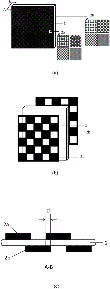
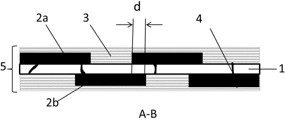
[0034] In this embodiment, the bipolar current collector includes: the conductive matrix film 1 is a polymer composite conductive film composed of conductive fillers and polymer matrix materials; the polymer barrier film layers 2a and 2b are made of polyvinylidene fluoride; the conductive shunt layer 3 Composite coating of carbon black and polyvinylidene fluoride is used.

[0035] The preparation method of the bipolar current collector of the present embodiment is as follows:

[0036] 1) Pretreatment of the conductive substrate film:

[0037] Take a polymer composite conductive film with a thickness of 35 μm, cut it into A4 paper size, spray and clean the surface of the polymer composite conductive film with deionized water and ethanol respectively, remove dust and oil on the surface, and dry it with hot air for 1 min.

[0038] 2) Print the polymer barrier film layer:

[0039] a. Ink preparation for polymer barrier film layer printing: in terms of mass percentage: polyvinyl...

Embodiment 2

[0044] In this embodiment, the bipolar current collector includes: the conductive matrix film 1 adopts a polymer composite conductive film composed of a conductive filler and a polymer matrix material; the polymer barrier layers 2a and 2b adopt polyaniline; the conductive shunt layer 3 adopts carbon black and polyvinylidene fluoride composite coating.

[0045] In the preparation process of the bipolar current collector, the polymer barrier layer adopts the conductive polymer polyaniline. Its ink formula: all use mass percentage, 0.125g polyaniline / 20ml 1% sulfuric acid solution, humectant glycerol 5%, 1% OP-10 aqueous solution 2%, stir at room temperature for 4h, ultrasonic treatment for 30min, and multi-stage filtration Impurities with a particle size greater than 0.2 μm are removed to obtain printing ink. All the other are identical with embodiment 1 preparation method

Embodiment 3

[0047] In this embodiment, the bipolar current collector includes: the conductive matrix film 1 is a polymer composite conductive film composed of conductive fillers and polymer matrix materials; the polymer barrier layers 2a and 2b are made of polystyrene; the conductive shunt layer 3 is made of carbon Black and polyvinylidene fluoride composite coating.

[0048] In the preparation process of the bipolar current collector, the polymer barrier layer is made of polystyrene, and its ink formula: all use mass percentage, polystyrene 2%, humectant glycerin 5%, 1% OP-10 aqueous solution 2% , the remaining amount of toluene, stirred at room temperature for 4 hours, ultrasonically treated for 30 minutes, and removed impurities with a particle size greater than 0.2 μm by multi-stage filtration to obtain printing ink. All the other preparation methods are the same as in Example 1.


PUM

PropertyMeasurementUnit
thicknessaaaaaaaaaa
thicknessaaaaaaaaaa
thicknessaaaaaaaaaa

Abstract

The invention provides a bipolar current collector and a preparation method thereof. The bipolar current collector comprises a conductive substrate film, polymer barrier film layers and conductive shunting layers, wherein upper and lower surfaces of the conductive substrate film are covered with the polymer barrier film layers and the conductive shunting layers, and the polymer barrier film layers are located between the conductive substrate film and the conductive shunting layers and cover upper and lower surfaces of the conductive substrate film in a staggered and complementary manner. The polymer barrier film layers can effectively prevent an electrolytic solution or a gel electrolyte from leaking in the bipolar current collector and prevent short circuits of a battery. Under the synergistic effect of two-sided complementary staggered covering structures of the polymer barrier film layers and the conductive shunting layers, the uniformity of the surface charge distribution of the bipolar current collector is improved, weakening caused by the polymer barrier film layers to the conductivity of the bipolar current collector is reduced to the greatest extent, and the surface contact resistance of the current collector is decreased; the bipolar current collector is prepared with an ink-jet printing method, and the method is efficient, energy-saving, clean and applicable to industrial production.

Description

technical field [0001] The invention belongs to the technical field of lithium ion batteries, and in particular relates to a bipolar current collector and a preparation method thereof. Background technique [0002] The development of electric vehicles is one of the effective means to alleviate problems such as energy crisis and environmental degradation. The key technology of electric vehicles lies in power batteries. Due to the advantages of high specific energy, high working voltage, long cycle life, low self-discharge, and no memory effect, lithium-ion batteries have attracted much attention as power batteries for electric vehicles. In order to improve the energy density of the power battery and meet the high power output requirements of the electric vehicle power source, a high-voltage power battery can be prepared by stacking series battery cells inside, and each series battery unit is separated by a bipolar current collector. Among them, the side of the bipolar curren...

Claims


Application Information

Patent Timeline
Patent Type & Authority Applications(China)
IPC IPC(8): H01M4/66
CPCH01M4/66H01M10/058Y02E60/10
Inventor 陈永翀何颖源张艳萍张萍王秋平
Owner BEIJING HAWAGA POWER STORAGE TECH
Why Eureka
Try Eureka