Energy-saving flue gas pollutant treatment system using waste heat of thermal power plant

A technology for pollutant treatment and thermal power plants, which is applied in heat pumps, climate sustainability, and reduction of greenhouse gases. It can solve the problems of high energy consumption of the flue gas ultra-low emission treatment system, and the heat cannot meet the flue gas reheater. Achieve the effects of reducing losses, reducing energy consumption and operating costs, and saving water resources

Active Publication Date: 2015-05-06
ZHEJIANG ZHENENG ENERGY SAVING TECH
View PDF6 Cites 12 Cited by
  • Summary
  • Abstract
  • Description
  • Claims
  • Application Information

AI Technical Summary

Problems solved by technology

When the thermal power unit is operating at full load, but in winter and other climates, the temperature of the exhaust gas flowing out of the air preheater is low or the thermal power unit is not operating at full load, resulting in low exhaust gas temperature and flue gas flowing out of the air preheater. When the flow rate is reduced, because the flue gas outlet temperature of the flue gas cooler and the flue gas reheater needs to be maintained at a state similar to that at full load, the heat obtained by the flue gas cooler cannot meet the needs of the flue gas reheater. Usually, it is necessary to add a certain amount of steam with certain parameters to heat the heat medium water flowing out of the flue gas cooler to ensure that the flue gas temperature at the outlet of the flue gas reheater reaches about 80°C
According to the actual operating experience of thermal power units that have been put into operation, when the load of thermal power units is lower, the amount of supplementary steam is more, and the energy consumption of the ultra-low emission treatment system for flue gas is greater

Method used


Image

  • Energy-saving flue gas pollutant treatment system using waste heat of thermal power plant

Examples


Embodiment 1

[0022] In this embodiment, the structure of the present invention is described in detail with reference to the drawings.

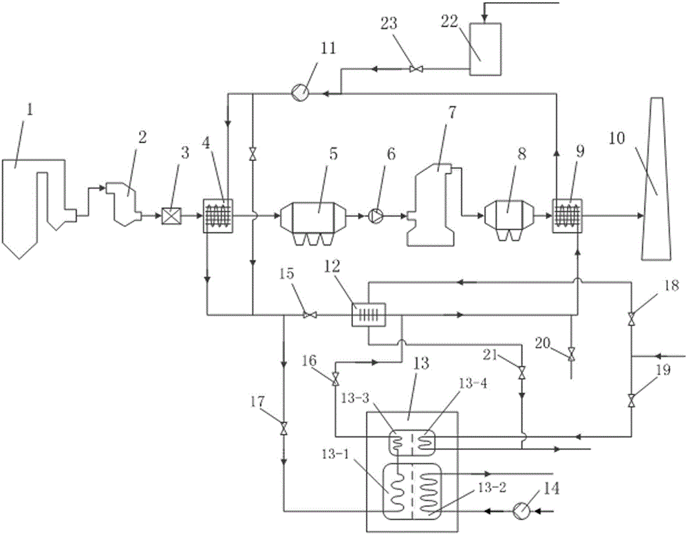
[0023] Referring to the accompanying drawings, the present invention provides an energy-saving flue gas pollutant treatment system utilizing waste heat from a thermal power plant, the system includes a flue gas cooler 4 and a flue gas reheater 9, and the flue gas cooler 4 and A steam auxiliary heater 12 is installed on the pipeline of the medium water circulation system between the flue gas reheaters 9. The function of the steam auxiliary heater 12 is to mix the supplementary steam with the medium water and send it to the flue gas when the boiler is running at low load. A reheater 9, an energy-saving branch circuit utilizing waste heat from a thermal power plant is also provided between the flue gas cooler 4 and the flue gas reheater 9 .

[0024] The energy-saving branch is provided with a first-type absorption heat pump 13, and the first-type absorption h...

Embodiment 2

[0037] heat balance mode of operation, such as figure 1 As shown, after the flue gas is discharged from the boiler 1, it passes through the SCR denitrification reactor 2, the air preheater 3, the flue gas cooler 4, the electrostatic precipitator 5, the induced draft fan 6, the FGD desulfurization tower 7, and the wet electrostatic precipitator 8 (may or may not be provided), flue gas reheater 9, and finally discharge through chimney 10. When the boiler is running at full load, the heat released by the flue gas cooler 4 meets the heat required by the flue gas reheater 9, the first type of absorption heat pump 13 stops, the valve 15 is opened, and the valves 17, 16, 18 and 19 are closed , the booster pump 11 is running, and the flue gas pollutant treatment system provided by the present invention is running in a heat self-balance state.

Embodiment 3

[0039] In the working mode of the energy-saving branch, the flow of flue gas pollutants is consistent with that in Embodiment 2, and Embodiment 1 and Embodiment 2 are combined.

[0040] When the heat released by the flue gas cooler cannot meet the heat required by the flue gas reheater when the boiler is not operating at full load, the controller of the first type of absorption heat pump 13 receives the signal from the control system of the flue gas co-processing system Start, valves 15 and 18 are closed, valves 17, 16 and 19 are opened, water diversion pump 14 is opened, and booster pump 11 runs. According to the flue gas inlet and outlet flow, temperature and medium water inlet and outlet flow, temperature, steam parameters of the flue gas cooler and flue gas reheater, the temperature of the open cycle cooling water or closed cooling water is automatically adjusted to enter the generator 13- 4 steam flow rate and the open-type circulating cooling water or closed-type cooling...


PUM


Abstract

The invention provides an energy-saving flue gas pollutant treatment system using waste heat of a thermal power plant. The energy-saving flue gas pollutant treatment system comprises a flue gas cooler, a flue gas re-heater and a steam auxiliary heater, wherein an energy-saving branch for utilizing the waste heat of the thermal power plant is further arranged between the flue gas cooler and the flue gas re-heater; the energy-saving branch is provided with a first type absorption heat pump; the first type absorption heat pump comprises an absorber, a condenser, an evaporator and a generator. By virtue of the energy-saving flue gas pollutant treatment system using the waste heat of the thermal power plant, provided by the invention, steam can be greatly saved and supplemented; the loss of circulating water is reduced by the first type absorption heat pump, so that water resources are saved, and the energy consumption and the operation cost of the operation of the pollutant treatment system are greatly reduced.

Description

technical field [0001] The invention relates to a thermal power plant pollutant treatment system, in particular to an energy-saving flue gas pollutant treatment system utilizing waste heat from a thermal power plant. Background technique [0002] With the improvement of air pollutant emission standards for thermal power plants in my country, all newly built, under construction and active thermal power units need to adopt advanced flue gas clean emission technology to achieve ultra-low emission of air pollutants. According to the current technical level, the co-processing process of flue gas pollutants based on flue gas cooling and reheating technology is recognized as the main technical route to achieve ultra-low emissions from coal-fired power plants. [0003] Its working principle is that the flue gas cooling and reheating technology includes two gas-water heat exchangers, one is the flue gas cooler, which is usually located on the flue between the air preheater and the el...

Claims


Application Information

Patent Timeline
Patent Type & Authority Applications(China)
IPC IPC(8): F23J15/02F23J15/06F23J15/08F25B30/06
CPCY02E20/30
Inventor 林少平张东明樊立安李煦侃杨晨钟金鸣
Owner ZHEJIANG ZHENENG ENERGY SAVING TECH
Why Eureka
Try Eureka