A Continuous Flow Rotary Shaft Reactor and Its Application

A technology of rotating shafts and reactors, which is applied in chemical/physical/physicochemical fixed reactors, chemical methods for reacting liquids with liquids, chemical methods for reacting liquids with gaseous media, etc., and can solve product purity, Influenced by particle size and distribution, it is not suitable for use by small processing enterprises, and it cannot react with materials, etc., to achieve the effect of simple structure and operation, large specific gravity, and easy precipitation

Active Publication Date: 2017-12-12
BEIJING UNIV OF CHEM TECH
View PDF4 Cites 0 Cited by
  • Summary
  • Abstract
  • Description
  • Claims
  • Application Information

AI Technical Summary

Problems solved by technology

For example, it is better to use a large-diameter, low-speed agitator for some operations; while another operation needs to operate a small-diameter, fast paddle, so that different types of agitators need to be replaced when producing different products, resulting in cumbersome operations and poor versatility.
In the processing of some food or medicine, it is often necessary to add some additives to the mother liquor, and then stir and heat. In the whole process, the feeding, stirring and temperature have strict control parameters, and the existing equipment has high cost. , complex control and other issues, it is not suitable for small processing enterprises, especially those with limited operating places
In addition, the composition will also change during the cooling process of the product, which may affect the purity, particle size and distribution of the product, etc.
Most stirred tanks cannot evenly stir materials with high specific gravity, high viscosity, and easy precipitation, and cannot fully mix and react the materials, so that the production requirements cannot be met.

Method used


Image

  • A Continuous Flow Rotary Shaft Reactor and Its Application
  • A Continuous Flow Rotary Shaft Reactor and Its Application

Examples


Embodiment 1

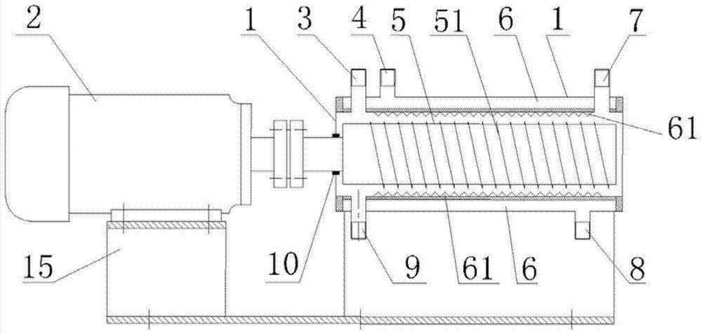
[0037] A continuous flow rotating shaft reactor, comprising a power unit 2 and a reactor body;

[0038] The power unit 2 is a motor;

[0039] The reactor body includes a shell 1, a jacket 6 and a rotating shaft 5. A jacket 6 is set inside the housing 1, and the jacket 6 surrounds the rotating shaft 5. The space between the rotating shaft 5 and the jacket 6 is The cavity is a reaction space 50;

[0040] A first material inlet 3 is provided on the upper part of the housing 1 close to the power device 2, a second material inlet 9 is provided on the symmetrical lower part, and a product outlet 7 is provided on the upper part of the housing 1 away from the power device 2;

[0041] The rotating shaft 5 is connected to the output shaft of the power unit 2; the rotating shaft 5 is installed horizontally; and the reactor and the power unit are all arranged on the support 15;

[0042] The 5-axis surface of the rotating shaft is smooth;

[0043] A seal 10 is provided between the rotat...

Embodiment 2

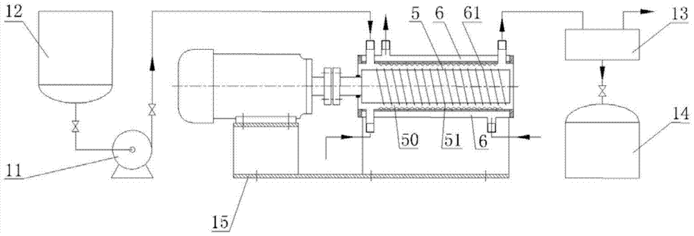
[0049] see figure 2 Shown, the application of a kind of continuous flow rotary shaft reactor of the present invention in multiphase flow reaction process, with gas-liquid reaction LiOH and CO 2 Reaction produces Li 2 CO 3 For example:

[0050] The ratio of the length of the rotating shaft to the radius of the cross-section used in the experiment is 10:1, and the rotating shaft reactor with a cavity volume of 50 L puts the LiOH solution in the raw material tank 12, and the solution will be pumped into the tank at 20 L / h with a volume of In the chamber of the 50L rotating shaft reactor, the pH value is adjusted to 9, and the CO 2The gas is passed into the cavity of the rotating shaft reactor, and the speed of the rotating shaft is adjusted to 500 rpm. The gas and liquid are fully contacted under the action of the guide thread of the rotating shaft, and the mixed precipitate is passed into a centrifuge for dehydration and washing, and then passed into a drying tank to adjust...

Embodiment 3

[0052] see figure 2 Shown, the application of a kind of continuous flow rotary axis reactor of the present invention in multiphase flow reaction process, with gas-liquid reaction LiOH and CO 2 Reaction produces Li 2 CO 3 as an example

[0053] The ratio of the length of the rotating shaft to the radius of the cross section used in the experiment is 10:1, and the rotating shaft reactor with a cavity volume of 50L puts the LiOH solution in the raw material tank, and the solution will be pumped into the 50L reactor at a rate of 12L / h by the action of the pump. In the cavity of the rotating shaft reactor, the pH value is adjusted to 10, and at the same time, the CO 2 The gas is passed into the chamber of the rotating shaft reactor, and the speed of the rotating shaft is adjusted to 400rpm. The gas and liquid are fully contacted under the action of the guide thread of the rotating shaft, and the mixed precipitate is passed into a centrifuge for dehydration and washing, and the...


PUM


Abstract

The invention discloses a continuous flow rotating shaft reactor, which comprises a power apparatus and a reactor body; the reactor body comprises a casing, a jacket and a rotating shaft, the jacket is arranged in the casing, the jacket is capable of encircling the rotating shaft, a chamber between the rotating shaft and the jacket is a reaction space; at least two material inlets and at least a products outlet which are communicated to the reaction space are arranged on the casing; at least a thermal medium inlet and at least a thermal medium outlet which are communicated to the jacket are arranged on the casing; and the rotating shaft is connected to the output shaft of the power apparatus. The continuous flow rotating shaft reactor can realize accurate control of temperature, full mixing and stirring of materials; and has the advantages of uniform mixing, high product purity, large yield, strong versatility, and simple structure and operation, and is especially suitable for a multiphase flow (gas-liquid, liquid-liquid, and gas-liquid-solid)reaction system of materials with characteristics of large ratio, large viscosity, easy precipitation and long standing time.

Description

technical field [0001] The invention relates to a continuous flow rotating shaft reactor and its application, in particular to a rotating shaft reactor capable of precise temperature control and sufficient mixing and stirring and its reaction in multiphase flow (gas-liquid, liquid-liquid, gas-liquid solid) system applications. It is especially suitable for multiphase flow reactions with large specificity, high viscosity, easy precipitation and long residence time, and belongs to the field of high gravity technology. Background technique [0002] Hypergravity technology is based on the gravity acceleration (9.8m / s) of the earth 2 ) A high-tech technology produced in a much larger environment. Rotating packed bed (i.e. supergravity machine, RPB) is the core equipment for realizing supergravity technology, and it is also a new type of equipment that enhances interphase mass transfer and multiphase mixing. As early as 1983, the British Imperial Chemical Industries Company suc...

Claims


Application Information

Patent Timeline
Patent Type & Authority Patents(China)
IPC IPC(8): B01J19/20B01J8/10B01J10/00B01J14/00
CPCB01J8/10B01J10/00B01J14/00B01J19/20B01J2208/00867B01J2219/182
Inventor 陈建峰桑乐初广文罗勇邹海魁
Owner BEIJING UNIV OF CHEM TECH
Why Eureka
Try Eureka