Device for improving rotary table chopper Q-switch laser performance and a Q-switch laser

A technology of lasers and laser beams, applied in the field of lasers, can solve problems such as unfavorable laser Q-switching fast switching process, optical frequency breakdown, and reduce the volume of laser oscillation modes, so as to maintain the selection characteristics of transverse modes, expand the volume of fundamental modes, Avoid the effect of optical frequency breakdown

Active Publication Date: 2015-06-10
HUAZHONG UNIV OF SCI & TECH
View PDF7 Cites 8 Cited by
  • Summary
  • Abstract
  • Description
  • Claims
  • Application Information

AI Technical Summary

Problems solved by technology

However, this method has a defect in the implementation of turntable chopper Q-switching for lasers with large aperture, high energy, and fast laser build-up time: if the diameter of the through-hole is larger than the diameter of the laser medium (usually selected), it will cause the opening time of the Q switch If the diameter of the optical hole is smaller than the diameter of the laser medium, although the opening time of the Q switch can be reduced, it will increase the useless loss of laser power and reduce the laser oscillation. The mode volume of the laser medium cannot be fully utilized
Although these two methods can reduce the diameter of the optical hole of the chopper turntable and shorten the switching time of the Q switch under the condition of constant motor speed, the following problems still exist in practical applications: The focus has a serious impact on the chopping of the turntable, especially in the case of high power, the light intensity in the cavity is too strong, it is easy to produce the phenomenon of optical frequency breakdown, destroy the laser oscillation condition, cause the laser to have no output, and in serious cases, it will damage the optical components or chopping. Wave turntable

Method used


Image

  • Device for improving rotary table chopper Q-switch laser performance and a Q-switch laser
  • Device for improving rotary table chopper Q-switch laser performance and a Q-switch laser
  • Device for improving rotary table chopper Q-switch laser performance and a Q-switch laser

Examples


Embodiment 1

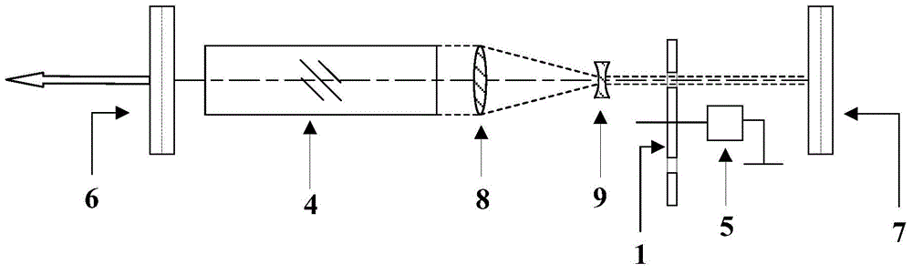
[0032] figure 1 is a schematic structural diagram of a Q-switched laser according to the first embodiment of the present invention. Such as figure 1 As shown, in the parallel plane cavity composed of the output mirror 6 and the total reflection mirror 7, the laser medium 4, the first Galilean telescope device, and the turntable chopper Q-switching device are sequentially distributed. The turntable chopper Q-switching device includes a high-speed motor 5 and a chopper turntable 1 driven by the high-speed motor 5 to rotate. On the edge of the chopper turntable 1, light holes 3 for the passage of laser beams are arranged at equal intervals in a circular array. The first Galilean telescope device consists of a convex lens 8 and a concave lens 9 . Driven by the high-speed motor 5, the chopper turntable 1 rotates to change the Q value of the cavity, and the chopper turntable 1 periodically opens or blocks the optical path to realize Q-switching. The Galilean telescope device does...

Embodiment 2

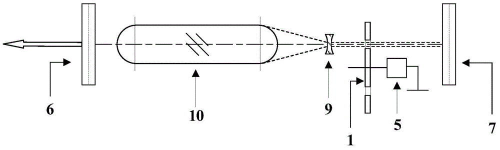
[0035] figure 2 is a schematic structural diagram of a Q-switched laser according to the second embodiment of the present invention. Such as figure 2 As shown, its structural principle is the same as figure 1 The first shown embodiment is similar, except that the thermal lens formed by the thermal lens effect of the laser medium is used to replace the function of the convex lens in the first Galilean telescope device. In this embodiment, the laser medium (equivalent thermal lens) 10 and concave lens 9 form a light beam compression device, which simplifies the structure and reduces additional insertion loss.

Embodiment 3

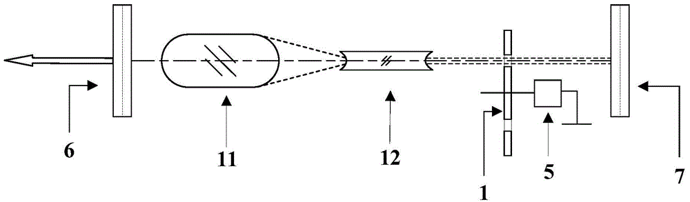
[0037] image 3 is a schematic structural diagram of a Q-switched laser according to the third embodiment of the present invention. Such as image 3 As shown, in the parallel plane cavity composed of the output mirror 6 and the total reflection mirror 7, the double-convex curvature end face laser medium 11, the double-concave curvature laser medium 12 and the turntable containing the chopper turntable 1 and the high-speed motor 5 are distributed in sequence chopping Q-switching device. The method of rotary disk chopping Q-modulation is the same as that of the first embodiment. The first Galilean telescope device is composed of a double convex curvature end face laser medium 11 and a double concave curvature end face laser medium 12 . The double-convex curvature end laser medium 11 has a positive curvature radius processed on both ends to achieve the optical effect of a convex lens, and the double-concave curvature end laser medium 11 has a negative curvature radius processe...


PUM


Abstract

The invention discloses a device for improving rotary table chopper Q-switch laser performance and a Q-switch laser. The device comprises Galileo telescope units located inside or outside a resonant cavity and a rotary table chopper Q-switched component located inside the resonant cavity and used for performing Q-switch on a compressed laser beam; when the number of laser media is one, the first Galileo telescopic unit is located inside the resonant cavity and used for compressing the diameter of the compressed laser beam so as to reduce Q-switching time and enhance Q-switch effect; when the number of the laser media is more than one, the second Galileo telescopic unit located outside the resonant cavity is shared by various laser resonant cavities and used for subjecting the Q-switch laser to beam combination, and superposition output of incoherent light wave is realized; when the number of the laser media is more than one which is an even number, superposition output of quasi-coherent light wave is realized by the aid of a polyhedron prism and the third Galileo telescopic unit located in the laser resonant cavity. The device is of active effects on narrow pulse width and large-energy Q-switch laser generated by the aid of a shopper rotary table.

Description

technical field [0001] The invention relates to the field of laser technology, in particular to a device and a Q-switched laser for improving the chopping Q-switching performance of a laser turntable. Background technique [0002] Laser Q-switching is one of the main technical methods to generate narrow pulse and high peak power laser. Compared with electro-optic, acousto-optic and passive Q-switching methods, rotary-disk chopper Q-switching has the advantages of good turn-off effect, simple structure, no additional absorption loss and useless loss, no wavelength and polarization selectivity, and high power tolerance. [0003] In 1996, Chin-Lin Chen indicated in the book "Elements Of Optoelectronics And Fiber Optics" that the Q-switching method of the laser mechanical chopper (Rotation Chopper) refers to inserting a rotating chopper in the laser cavity, chopping The wave turntable is driven by a high-speed motor, and there are several slits or small holes on its edge. When ...

Claims


Application Information

Patent Timeline
Patent Type & Authority Applications(China)
IPC IPC(8): H01S3/08H01S3/06H01S3/07H01S3/121
Inventor 朱晓田佳王海林齐丽君郭飞朱广志朱长虹王珂
Owner HUAZHONG UNIV OF SCI & TECH
Why Eureka
Try Eureka