System and method for reducing sulfur dioxide emission concentration of sulfur recovery device and desulfurization agent

A sulfur dioxide and sulfur recovery technology, applied in chemical instruments and methods, separation methods, sulfur preparation/purification, etc., can solve the problems of high energy consumption, reduce sulfur dioxide emission concentration of sulfur recovery devices, etc., achieve low investment and save operating costs , the effect of low operating costs

Inactive Publication Date: 2015-07-22
WUHAN GLT ENERGY & ENVIRONMENTAL TECH CO LTD
View PDF9 Cites 8 Cited by
  • Summary
  • Abstract
  • Description
  • Claims
  • Application Information

AI Technical Summary

Problems solved by technology

[0011] Obviously, the above-mentioned disclosed methods either have high energy consumption and are greatly affected by the tail gas composition, or do not combine the complex iron wet oxidation desulfurization method with the composition characteristics of the ta...

Method used


Image

  • System and method for reducing sulfur dioxide emission concentration of sulfur recovery device and desulfurization agent
  • System and method for reducing sulfur dioxide emission concentration of sulfur recovery device and desulfurization agent

Examples


no. 1 approach

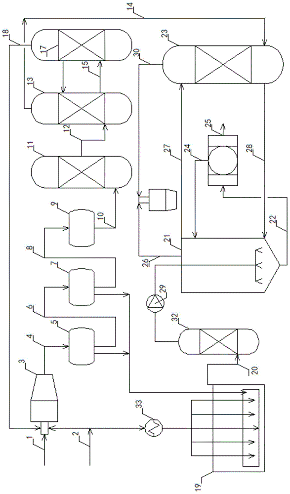
[0049] like figure 1 As shown, the system for reducing the emission concentration of sulfur dioxide from the sulfur recovery unit includes: complex iron desulfurization unit, sulfur recovery unit, and liquid sulfur pool gas stripping unit.

[0050] The sulfur recovery unit includes a reaction furnace 3 , a primary converter 5 , a secondary converter 7 , a hydrogenation reactor 9 , a quenching tower 11 , an amine absorption tower 13 , and an amine absorption regeneration tower 17 connected in sequence. Acid gas 1 and air 2 are sequentially transformed into reactor tail gas 4 , primary reformer tail gas 6 , secondary reformer tail gas 8 , hydrogenation tail gas 10 , quenching tail gas 12 and amine suction tail gas 14 . The amine absorption rich liquid 15 enters the amine absorption regeneration tower 17 .

[0051] The gas stripping device in the liquid sulfur pool includes an air heater 33 , a liquid sulfur pool 19 and a tail gas scrubber 32 connected in sequence. The tail gas...

no. 2 approach

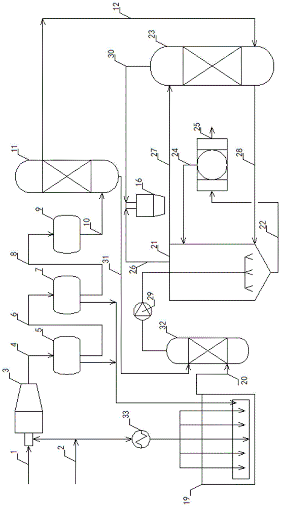
[0055] like figure 2 As shown, the system for reducing the emission concentration of sulfur dioxide from the sulfur recovery unit includes: complex iron desulfurization unit, sulfur recovery unit, and liquid sulfur pool gas stripping unit.

[0056] The sulfur recovery unit includes a reaction furnace 3 , a primary converter 5 , a secondary converter 7 , a hydrogenation reactor 9 and a quench tower 11 connected in sequence. Acid gas 1 and air 2 are transformed into reaction furnace tail gas 4 , primary reformer tail gas 6 , secondary reformer tail gas 8 , hydrogenation tail gas 10 , and quenching tail gas 12 in turn.

[0057] The gas stripping device in the liquid sulfur pool includes an air heater 33 , a liquid sulfur pool 19 and a tail gas scrubber 32 connected in sequence. The tail gas 20 from the liquid sulfur pool stripping enters the liquid sulfur pool stripping tail gas scrubber 32 . Before the liquid sulfur pool 19, an air heating device 33 can be arranged. A booste...

Embodiment 1

[0061] A 40,000-ton / year sulfur recovery unit of a petrochemical company, in figure 1 In the system, the exhaust gas volume at the outlet of quench tower 11 is 12636Nm 3 / h, the hydrogen sulfide content is 2.18%v, the temperature is 70°C, and the pressure is 0.012Mpa. The factory compressed air enters the liquid sulfur pool degassing system 19 after being heated, and the stripping tail gas 20 degassed from the liquid sulfur pool passes through the scrubber 32 with a gas volume of 650Nm 3 / h, the average hydrogen sulfide content is 320ppmv, the temperature is 70°C, and the pressure is increased to 0.035Mpa. Stop the tail gas amine suction system of the original sulfur recovery unit, and enter the exhaust gas 12 of the quenching tower into the absorption tower 23 of the complexed iron desulfurization system. Countercurrent contact in tower 23, purified tail gas 30 goes to incinerator 16. The exhaust gas 20 from the liquid sulfur tank is passed through the water washing tower ...


PUM


Abstract

The invention belongs to the technical field of sulfur recovery and particularly relates to a system and a method for reducing sulfur dioxide emission concentration of a sulfur recovery device and a desulfurization agent. The desulfurization agent comprises aminopolycarboxylic acid chelate iron, an aminopolycarboxylic acid chelating agent, acrylamide and fatty alcohol polyoxyethylene ether-9 and water. The system comprises a complex iron desulfurization device, the sulfur recovery device and a liquid sulfur tank gas stripping device; tail gas generated by degassing of a liquid sulfur tank and the sulfur recovery device is purified in a complex iron desulfurization system, so that various factors causing sulfur dioxide emission of the sulfur recovery device are radically eliminated from the source; the sulfur dioxide concentration of flue gas after incineration is guaranteed to be lower than 50 mg/Nm<3>; thermal reaction and conversion parts of an existing sulfur recovery device are not changed, so that the investment is low and the running cost is low; air is utilized for degassing of the liquid sulfur tank and serves as regeneration air of the complex iron desulfurization system, so that the running cost of liquid sulfur degassing purification is reduced; a comprehensive and complete solution is provided for reducing the sulfur dioxide emission concentration of the sulfur recovery device.

Description

technical field [0001] The invention belongs to the technical field of sulfur recovery, and in particular relates to a system, a method and a desulfurizer for reducing the sulfur dioxide emission concentration of a sulfur recovery device. Background technique [0002] After the reform and opening up, China absorbed the core parts of advanced human civilization on a large scale, and released SO into the atmosphere in the industrial process. 2 In terms of the control of sulphur production units, China published in 1996 the SO 2 Emission standard, namely the current standard GB 16297-1996. This standard is for the process SO in oil refining, petrochemical, coal chemical and other fields. 2 In terms of emissions, it is currently higher than the standards of developed countries. The implementation of this standard nearly 20 years ago played an important role in solving the serious problems of atmospheric soot pollution and soil acidification in China at that time. [0003] Ac...

Claims


Application Information

Patent Timeline
IPC IPC(8): C01B17/04B01D53/75B01D53/48
Inventor 潘威刘斯洋祝茂元张娜周志雄
Owner WUHAN GLT ENERGY & ENVIRONMENTAL TECH CO LTD
Why Eureka
Try Eureka