Personalized minimally-invasive knee joint positioning guide plate based on medical image

A medical image, knee joint technology, applied in the field of medical devices, can solve problems such as unimaginable consequences, unstable navigation system, increased patient blood loss, etc., to reduce errors in prosthesis size selection and alignment of force lines Assembly and sterilization process time, avoid over-positioning and the effect of unstable positioning

Inactive Publication Date: 2015-07-29
SHANGHAI XINJIAN MEDICAL TECH
View PDF0 Cites 17 Cited by
  • Summary
  • Abstract
  • Description
  • Claims
  • Application Information

AI Technical Summary

Problems solved by technology

[0005] However, navigation technology also has some recognized disadvantages: ①Input of bony landmark points is required during the operation, which prolongs the operation time; ②The positioning of bony landmark points is still based on naked eye judgment and needs to rely on the experience of doctors ;③Navigation technology is to measure the force line of the lower limbs under the condition of non-weight bearing, and the result is different from that under weight bearing;④The patella is in a state of complete dislocation when the navigation technology measures, which does not help the osteotomy of the patella;⑤The navigation system itself has Instability, and the cost of surgery is high, and it is still difficult to promote widely in clinical practice
However, it cannot be denied that the robot-assisted surgery system still has some limitations: ①The cost of equipment is high, and operations such as installation, commissioning, and disinfection are relatively complicated; Accept fully automatic surgery; ③ There will be some problems with the anti-interference ability and stability of electronic instruments, once an emergency occurs, the consequences will be unimaginable; ④ The flexibility and accuracy of surgical operations still need to be improved; ⑤ Current surgical robots The speed of automatic bone cutting is very slow, prolonging the operation time and increasing the blood loss of patients
The fitting surface obtained in this way is the entire bone surface, and the fitting area is too large. In actual clinical practice, some soft tissues, ligaments, osteophytes, etc. will be attached to the bone surface, resulting in poor fitting effect, and the fitting position is not unique or cannot fit.

Method used


Image

  • Personalized minimally-invasive knee joint positioning guide plate based on medical image
  • Personalized minimally-invasive knee joint positioning guide plate based on medical image
  • Personalized minimally-invasive knee joint positioning guide plate based on medical image

Examples


Embodiment 1

[0032] The specific implementation steps are as follows:

[0033] Step 1, lower limb data acquisition: CT / MRI scan (or other medical imaging methods) is performed on the lower limb (or some structural features) of the patient, and the scanned data is saved in DICOM or other formats.

[0034] Step 2, 3D reconstruction of lower extremities: Import the acquired CT / MRI or other medical image data (or some structural features) of the patient into the 3D reconstruction software, and pre-process the 2D images by means of filtering, noise reduction, etc. The grayscale threshold is set for the contour, and the image segmentation is performed on the corresponding selected area on the transverse, coronal, and sagittal planes, and the 3D model of the lower extremity bones is reconstructed, which is saved as an STL or other format file.

[0035]Step 3, formulate preoperative planning: mark the characteristic reference points, lines, and surfaces of the lower limbs on the reconstructed 3D m...

Embodiment 2

[0040] Embodiment 2 introduces the steps and method of designing a composite positioning guide plate, in which steps 1-3 and 5 are the same as those in embodiment 1, and will not be repeated here, only steps 4 and 6 will be described in detail.

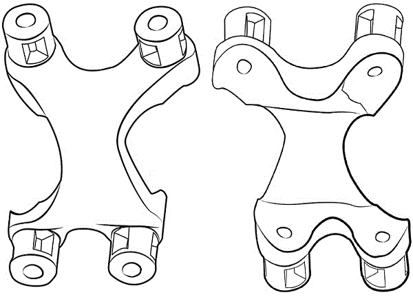
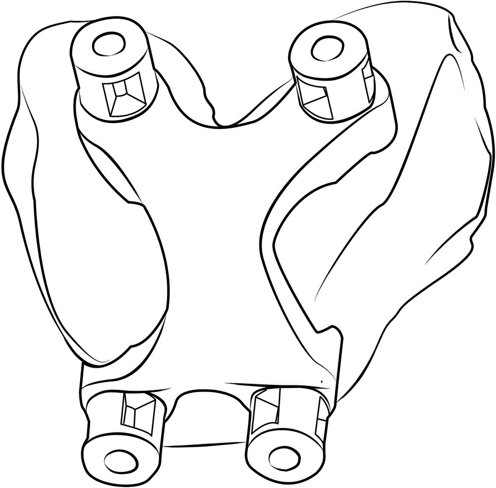
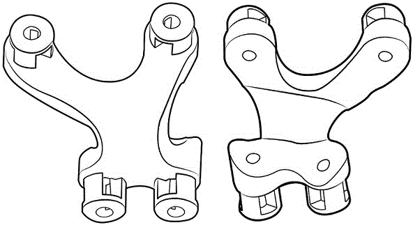
[0041] Step 4, design and manufacture of the positioning guide: according to the position of the femoral and tibial prosthesis and the size of the osteotomy determined by the above preoperative planning, determine the placement position of the four-in-one osteotomy, and then determine the placement position of the four-in-one osteotomy. The position of the positioning hole and the plane of the osteotomy were determined, and the axial position of the positioning hole of the composite positioning guide plate and the plane position of the osteotomy part were determined. On this basis, the main part of the composite positioning guide plate was designed through the forward design software, and then combined with the weight Carry out Boolean...


PUM


Abstract

The invention discloses a personalized minimally-invasive knee joint positioning guide plate used for knee arthroplasty and manufactured on the basis of medical image three-dimensional reconstruction and computer-aided design technologies, 3D (three-dimensional) printing or other machining methods, and particularly relates to accurate determination of a positioning joint surface. Firstly, a patient skeleton model is reconstructed on the basis of a two-dimensional medical image; preoperative planning is performed on the reconstructed model, and important parameters such as a lower extremity force line, a femoral rotation axis and an osteotomy reference point are determined to simulate osteotomy and prosthesis implantation; a positioning sheet (single positioning type and composite type) is determined and designed with the results. The positioning sheet is used for positioning with a local positioning principle by means of local area jointing, so that over-positioning and positioning instability are avoided; meanwhile, the wound area is reduced to the maximum extent. A dissection point is positioned through the reconstructed model, so that the lower extremity force line can be reconstructed accurately, and accurate osteotomy is realized.

Description

technical field [0001] The invention relates to the technical field of medical devices, in particular to a personalized minimally traumatic knee joint positioning guide plate for knee joint replacement surgery based on medical image three-dimensional reconstruction technology and computer-aided design technology, using 3D printing or other processing methods. Background technique [0002] Total knee arthroplasty (total knee arthroplasty, TKA) has become an effective method for surgical treatment of end-stage knee osteoarthritis, rheumatoid arthritis and other diseases. It can effectively relieve knee joint pain, correct lower limb deformities and improve knee pain. joint function. The key to TKR technology is to restore the normal anatomical force line of the lower limbs, deal with varus and varus of the knee joint, and reduce the occurrence of complications. [0003] However, the success of conventional TKR technology remains questionable. Generally speaking, the traditio...

Claims


Application Information

Patent Timeline
Patent Type & Authority Applications(China)
IPC IPC(8): A61B19/00A61B17/56
Inventor 刘非张明娇李涤尘
Owner SHANGHAI XINJIAN MEDICAL TECH
Why Eureka
Try Eureka