
Coal gas, converter steam and sintering waste heat combined power generation device and waste heat utilization method

A combined power generation and steam technology, applied in furnaces, waste heat treatment, furnace components, etc., can solve the problems of poor system stability, large investment, and high operation and maintenance costs

Inactive Publication Date: 2015-07-29
HUNAN ZHONGYE CHANGTIAN ENERGY CONSERVATION & ENVIRONMENTAL PROTECTION TECH CO LTD
View PDF5 Cites 4 Cited by
  • Summary
  • Abstract
  • Description
  • Claims
  • Application Information

AI Technical Summary

Problems solved by technology

In this way, a lot of waste heat is recovered, but setting up many scattered small waste heat back to power stations will bring two problems: one is that it occupies a lot of land, requires a large investment, and the operation and maintenance costs are high; on the other hand, part of the waste heat recovery Low thermal efficiency, poor system stability, high shutdown rate
This waste heat recovery method does improve the parameters of saturated steam, but it does not utilize the high-temperature exhaust smoke of the heating furnace, and the waste heat of sintering only uses the waste heat of the ring cooler, and the thermal efficiency of the system is low. Although it solves the problem of merging waste heat systems, But it does not improve the efficiency of waste heat utilization

Method used


Image

  • Coal gas, converter steam and sintering waste heat combined power generation device and waste heat utilization method
  • Coal gas, converter steam and sintering waste heat combined power generation device and waste heat utilization method
  • Coal gas, converter steam and sintering waste heat combined power generation device and waste heat utilization method

Examples


Embodiment 1

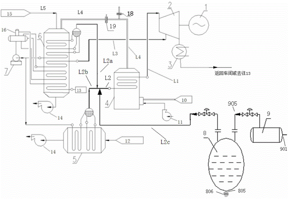
[0231] device such as figure 1 shown in . A coal gas, converter steam and sintering waste heat combined power generation device, the device includes a generator 1, a steam turbine 2, a condenser 3, a superheated afterburning furnace 4, a sintering smoke exhaust pipe waste heat boiler 5, an annular cooler waste heat boiler 6, a refinery A steel converter steam drum 9 and a converter steam regenerator 8 connected to the steelmaking converter steam drum 9 . Wherein: the low-parameter superheated steam outlet 60402 of the waste heat boiler 6 of the annular cooler is connected to the steam inlet 202 of the steam turbine. The high-parameter saturated steam output pipe L2a of the annular cooler waste heat boiler 6, the high-parameter saturated steam output pipe L2b of the sintered exhaust pipe waste heat boiler 5, and the high-parameter saturated steam output pipe L2c of the converter steam accumulator 8 are connected to the superheated afterburning The steam inlet 402 of the furna...

Embodiment 2

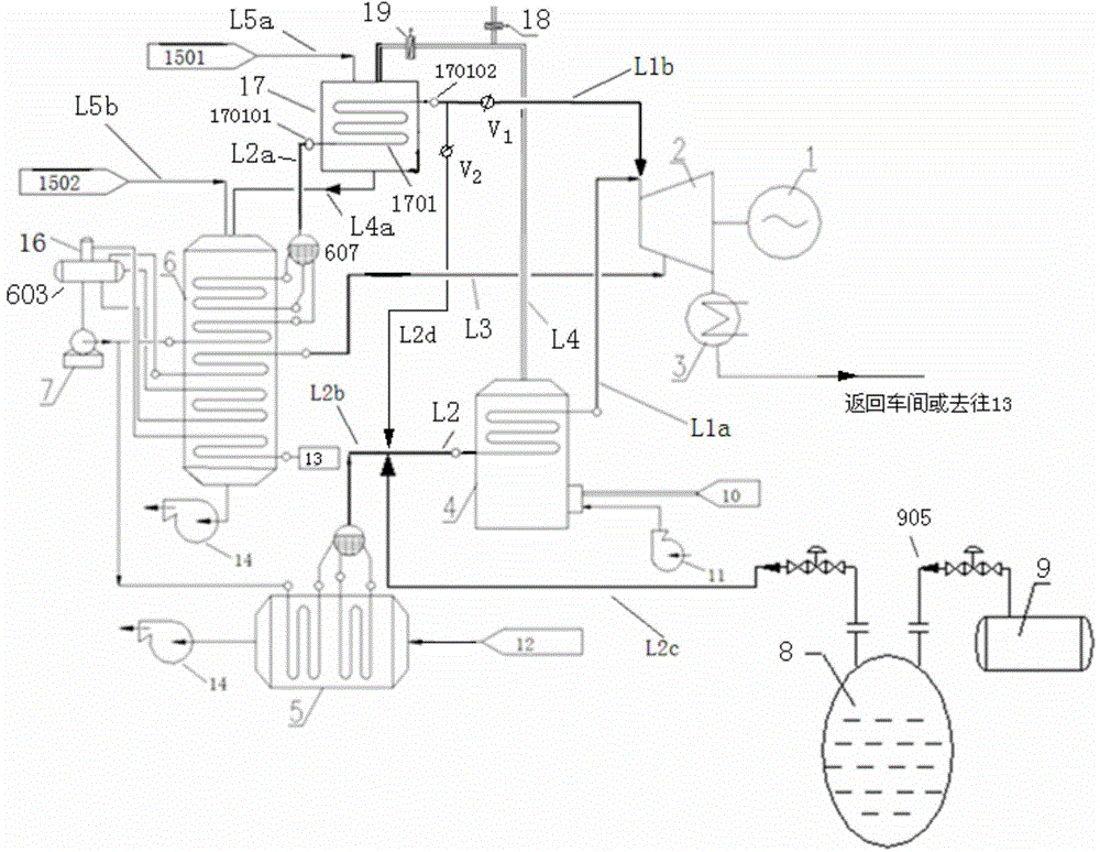
[0250] Such as figure 2 shown in . A coal gas, converter steam and sintering waste heat combined power generation device, the device includes a generator 1, a steam turbine 2, a condenser 3, a superheated afterburning furnace 4, a sintering exhaust pipe waste heat boiler 5, and a ring with an external superheating device 17 Cold machine waste heat boiler 6, steelmaking converter steam drum 9 and converter steam heat accumulator 8 connected with steelmaking converter steam drum 9. Wherein: the low-parameter superheated steam outlet 60402 of the waste heat boiler 6 of the annular cooler is connected to the steam inlet 202 of the steam turbine. The high-parameter saturated steam output pipe L2a of the waste heat boiler 6 of the annular cooler is connected to the inlet 170101 of the superheater 1701 of the external superheater 17, and is connected to the main steam inlet 201 or It is connected to the saturated steam inlet 402 of the superheated afterburning furnace through the ...

Embodiment 3

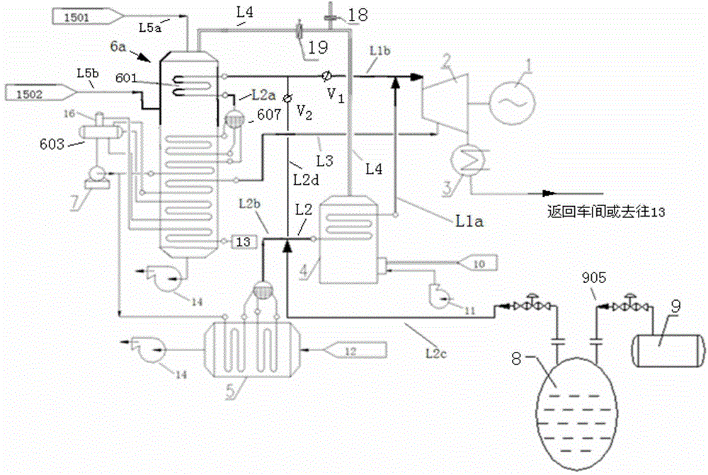
[0269] Such as image 3 shown in . A coal gas, converter steam and sintering waste heat combined power generation device, the device includes a generator 1, a steam turbine 2, a condenser 3, a superheated post-combustion furnace 4, a sintering exhaust pipe waste heat boiler 5, and a ring cooling system with a built-in superheater 610 Machine waste heat boiler 6, steelmaking converter steam drum 9 and converter steam heat accumulator 8 connected with steelmaking converter steam drum 9. Wherein: the low-parameter superheated steam outlet 60402 of the waste heat boiler 6 of the annular cooler is connected to the steam inlet 202 of the steam turbine. The high-parameter saturated steam output pipe L2a of the waste heat boiler 6 of the ring cooler is connected to the inlet 61001 of the built-in superheater 610 of the waste heat boiler of the ring cooler, and the outlet 61002 of the superheater 610 of the waste heat boiler of the ring cooler passes through the superheated steam pipe...


PUM


Abstract

The invention relates to a coal gas, converter steam and sintering waste heat combined power generation device which comprises a generator 1, a turbine 2, a condenser 3, an over-heat compensation combustion furnace 4, a waste heat boiler 5 of a sintered smoke exhaust pipe, a waste heat boiler 6 of a circular cooler, a steel converter drum 9 and a steam accumulator 8 of the converter, wherein low parameter over-heated steam generated by the waste heat boiler 6 of the circular cooler is connected with a steam compensation opening 202 of the turbine, high parameter saturated steam generated by the waste heat boiler 5 of the sintered smoke exhaust pipe and the steam accumulator 8 of the converter enters into a main steam inlet 201 of the turbine through the over-heat compensation combustion furnace 4, and a rotary shaft 204 of the turbine 2 is connected with or drives a rotary shaft of the generator 1. The coal gas, converter steam and sintering waste heat combined power generation device provided by the invention has the advantages that residual coal gas, sintered waste heat and converter steam of an iron and steel plant are comprehensively utilized, the utilization ratio of waste heat is high, the system is flexible, the outage rate of a steam turbine unit is low, and the investment and operation costs are low.

Description

technical field [0001] The present invention relates to a waste heat power generation system, in particular to a coal gas, converter steam and sintering waste heat combined power generation system, in particular to a coal gas, converter steam and sintering waste heat combined power generation device and a waste heat utilization method or a method of generating electricity. Background technique [0002] Iron and steel enterprises are energy-intensive enterprises with huge energy consumption, accounting for about 16% of the country's total energy consumption. The energy utilization rate is 30% to 50%, and the energy consumption per ton of steel is about 20% higher than that of developed countries. In the process of iron and steel production, a large amount of gas, high-temperature flue gas, and steam are produced, and a large part of waste heat and energy can be recycled. [0003] At present, the gas recovered by most large iron and steel plants is mainly used as fuel for the...

Claims


Application Information

Patent Timeline
Patent Type & Authority Applications(China)
IPC IPC(8): F27D17/00C21C5/46
CPCY02P10/25
Inventor 胡风华徐忠彭杰刘媛周响球
Owner HUNAN ZHONGYE CHANGTIAN ENERGY CONSERVATION & ENVIRONMENTAL PROTECTION TECH CO LTD
Learn More