Revivification method for catalytic cracking waste catalyst

A waste catalyst and catalytic cracking technology, which is applied in the direction of catalyst regeneration/reactivation, physical/chemical process catalysts, chemical instruments and methods, etc., can solve the problems of limited resurrection effect and complicated process, and achieve the reduction of coke yield and increase of liquid Yield, the effect of improving the yield of low-carbon olefins

Active Publication Date: 2015-08-05
于向真
View PDF8 Cites 15 Cited by
  • Summary
  • Abstract
  • Description
  • Claims
  • Application Information

AI Technical Summary

Problems solved by technology

[0003] The spent catalyst contains about 1~4% of rare earth oxide, 2000~5000ppm of V, 3000~8000ppm of Ni, 1000~4000ppm of Fe, Ca, Cu, etc. It belongs to solid waste. Materials used as fillers, or paved asphalt roads or cement roads, etc.; there are few reports at

Method used


Image

  • Revivification method for catalytic cracking waste catalyst
  • Revivification method for catalytic cracking waste catalyst
  • Revivification method for catalytic cracking waste catalyst

Examples


Embodiment 1

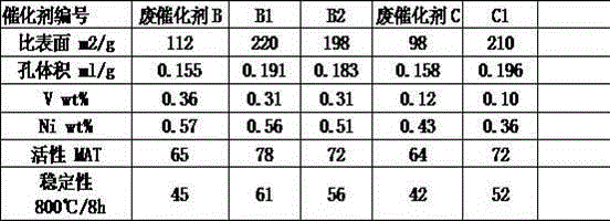
[0034] Take 500g of FCC spent catalyst A and place it in a 2000ml beaker, add 600ml of deionized water, add 100g of solid ammonium chloride, add 200ml of fluorosilicic acid solution with a concentration of 8%wt, add hydrochloric acid to adjust the pH value to 2.5, then stir and heat up to 80 ℃, constant temperature for 2 hours; filter and wash with 500ml of deionized water; add 600ml of rare earth chloride solution with rare earth oxide concentration of 100g / L, stir and mix for 30 minutes, filter and dry, and roast at 500℃ for 2 hours; Ammonium phosphate 1%wt solution, stirred for 30 minutes, filtered and dried to obtain the revived catalyst, record A1.

Embodiment 2

[0036] Take FCC waste catalyst A500g and place it in a 2000ml beaker, add 600ml of deionized water, add 100g of solid ammonium chloride, add 200ml of fluorosilicic acid solution with a concentration of 8%wt, add 50g of solid oxalic acid, add nitric acid to adjust the pH value to 2.8, and then Stir and heat up to 80°C, keep the temperature constant for 2 hours; filter, wash with 500ml of deionized water; add 500ml of rare earth chloride solution with a rare earth oxide concentration of 100g / L, stir and mix for 30 minutes, filter and dry, and roast at 500°C for 2 hours Add 400ml of solution containing ammonium phosphate 1%wt, add 500ml of deionized water, stir for 30 minutes, filter and dry to obtain the revived catalyst, record A2.

Embodiment 3

[0038] Take 500g of FCC waste catalyst A and place it in a 2000ml beaker, add 800ml of deionized water, add 130g of solid ammonium chloride, add 300ml of fluorosilicic acid solution with a concentration of 8%wt, add hydrochloric acid to adjust the pH value to 2.3, then stir and heat up to 80 ℃, constant temperature for 2 hours; filter and wash with 500ml deionized water; add 800ml of rare earth chloride solution with rare earth oxide concentration of 100g / L, stir and mix for 30 minutes, filter and dry, and roast at 500℃ for 2 hours; Ammonium phosphate 1%wt solution, stirred for 30 minutes, filtered and dried to obtain the revived catalyst, record A3.


PUM


Abstract

The invention relates to a revivification method for a catalytic cracking waste catalyst, which is characterized in that composite acid and ammonium salt are treated, and at least one of a supported rare earth treatment process and a phosphorus-containing acid treatment process is employed. a principle is characterized in that by improving a tunnel structure of the catalyst, composite acid is used for dredging the tunnel of the catalyst, a part of structure of molecular sieve is reconstructed through reaction and calcinations, acidity of the catalyst is adjusted by a rare earth compound-containing and/or phosphate-containing compound, so that waste catalyst performance can be recovered, the specific surface and activity of the recovered catalyst can be obviously increased, stability is obviously increased, good liquefied gas and low carbon olefin selectivity can be presented, green coke is reduced, liquid recovery is increased, gasoline RON is increased by 0.5-3 points, propylene and butylene yield can be respectively increased by more than 20-40% and 10-30%.

Description

technical field [0001] The invention relates to a method for revitalizing spent catalytic cracking catalysts, which belongs to the field of waste treatment and reuse. Background technique [0002] Fluid catalytic cracking (FCC) is one of the most important processing methods in petroleum processing. It is to crack heavy raw oil into light oil and liquefied gas at high temperature and under the action of a catalyst. Because the raw oil processed is different or Different target products are subdivided into wax oil catalysis, heavy oil catalysis (RFCC), DCC process, etc., but the process must use catalysts containing molecular sieves. Commonly used molecular sieves include Y-type molecular sieves, ZSM-5 molecular sieves, beta molecular sieves, etc. Due to the high temperature in the reaction process, water vapor and the deposition of metals brought by raw materials on the catalyst, the catalyst initially loses its activity, and some parts become thinner and lost due to wear and ...

Claims


Application Information

Patent Timeline
IPC IPC(8): B01J38/00B01J38/66B01J38/60B01J38/62B01J38/68B01J38/02
Inventor 于向真
Owner 于向真
Why Eureka
Try Eureka