
Solidifying and melting composite material increase forming method suitable for complex parts

A technology for additive forming and complex parts, applied in the field of additive forming of parts, which can solve the problems of low material utilization rate, high operating cost, poor forming quality of parts, etc., and achieves no arc radiation pollution, good working conditions, and stable formability. Effect

Active Publication Date: 2015-08-12
HUAZHONG UNIV OF SCI & TECH
View PDF6 Cites 18 Cited by
  • Summary
  • Abstract
  • Description
  • Claims
  • Application Information

AI Technical Summary

Problems solved by technology

Different fusion additive methods have their own advantages and disadvantages. For example, laser rapid prototyping technology, because all materials have to undergo a solid-liquid-solid phase transition process, resulting in large volume changes, large residual stress and deformation, and the need for high-power laser equipment, cost Higher, low deposition efficiency; electron beam rapid prototyping technology, due to the large impact of electron beams on powder, is not conducive to forming, and the forming process must be carried out in a vacuum chamber, which has high requirements for hardware and high operating costs; laser beam, plasma The parts formed by the beam and arc are not supported, and the complexity is limited; in addition, due to the low manufacturing accuracy and arc radiation, the scope of its industrial application is limited
[0004] The solid-state additive forming method mainly includes the "Ultrasonic Additive Manufacturing (UAM)" method developed by Fabrisonic in Germany. This method uses ultrasonic vibration energy to rub two surfaces to be connected to form an additive manufacturing process of intermolecular fusion. Although it has the advantages of small deformation and high precision, it still has the following problems: when the prepared parts need to meet the high-precision requirements, in addition to the ultrasonic forming device, it is also necessary to set up a three-axis CNC milling machine to process the parts after ultrasonic additive forming. Carry out mechanical processing, which increases equipment weight, manufacturing cycle and cost. At present, this method can only be used for additive forming of low melting point metals
[0005] In the existing rapid prototyping method for metal laminated solid manufacturing, the sheet material larger than the maximum size of the part is laid out as a whole, and then most of the waste materials are removed by a laser cutting system. The contact area of ​​the material is large, resulting in a small resistance welding current power density, small welding thickness and low quality
And the application publication number CN103350321A, the patent literature published on October 16, 2013 discloses a method for additive manufacturing of metal parts based on contour features, although the method adopts the idea of ​​layering to carry out layered slices on the model of metal parts However, there are still the following problems: this method controls the feeding track of the sheet through the control command, the sheet is fed in layers, and the superposition welding of each layer of the part is mechanically completed, and it can only control the feeding path of the sheet , but cannot accurately process the inner and outer contours of each layer of sheet metal, the machining accuracy is low, and the forming quality of the parts is poor, so it is not suitable for the forming of parts with complex inner and outer contours

Method used


Image

  • Solidifying and melting composite material increase forming method suitable for complex parts
  • Solidifying and melting composite material increase forming method suitable for complex parts
  • Solidifying and melting composite material increase forming method suitable for complex parts

Examples


Embodiment 1

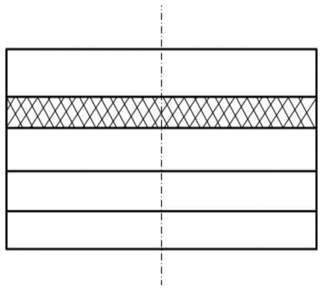
[0024] A solid-solution composite additive forming method suitable for solid cylindrical aluminum alloy parts as shown in Figure 1, which comprises the following steps:

[0025] (1) Referring to Fig. 1(a), establish the CAD geometric model of the part according to the three-dimensional shape and size of the target solid cylindrical aluminum alloy part, extract the STL model of the part, and select a layered thickness of 1.5mm according to the actual forming shape and size of the part; Referring to Fig. 1 (b) according to the STL model and layer thickness, the STL model is divided into 5 layers with a thickness of 1.5mm by the layered slicing software with a unit of 1.5mm. In this embodiment, layers 1-3 are selected Aluminum plate, insulating plate is used for the 4th layer, and copper plate is used for the 5th layer;

[0026] (2) Extract the inner and outer contour points of the STL model of each layer, and then perform filling processing based on these inner and outer contour...

Embodiment 2

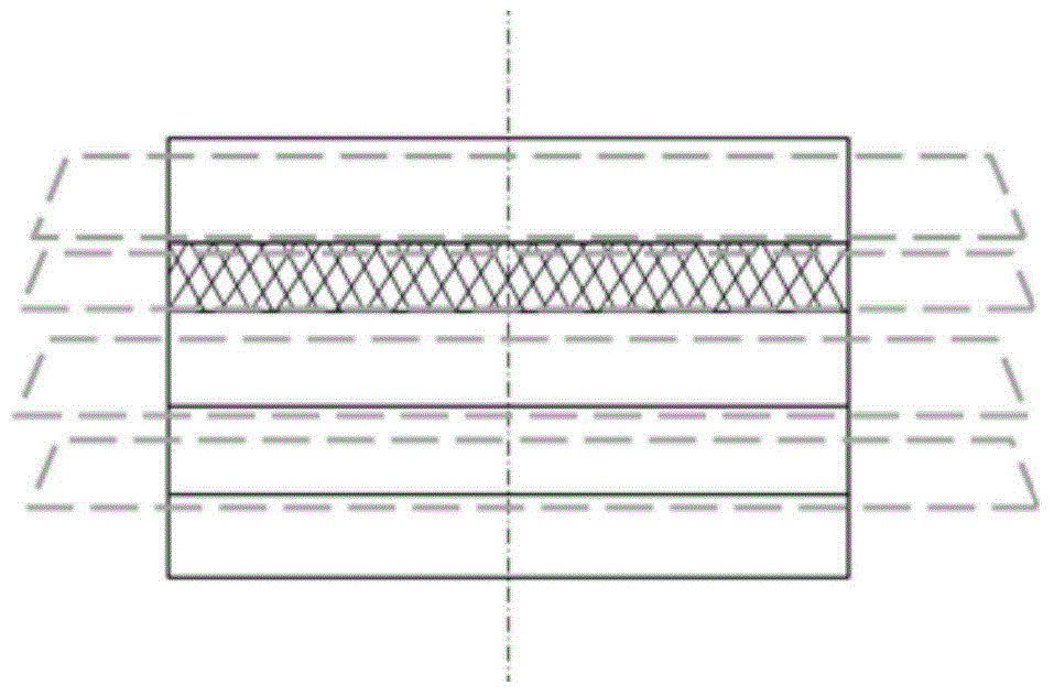
[0031] A solid-solution composite additive forming method suitable for complex metal parts with holes in the middle as shown in Figure 2, which includes the following steps:

[0032](1) Referring to Figure 2(a), the CAD geometric model of the part is established according to the three-dimensional shape and size of the target part, the STL model of the part is extracted, and the layer thickness is selected according to the actual shape and size of the part. In the actual operation process, the The layer thickness can be selected according to the actual needs. According to the shape and complexity of the part, the layer thickness of each layer can be the same or different, which is determined by the processing technology requirements of the part. The operator can make a reasonable selection and division according to the needs. In this embodiment, the layered thickness of each layer is selected to be 1mm; see Figure 2 (b) according to the STL model and layered thickness, the STL m...


PUM

PropertyMeasurementUnit
thicknessaaaaaaaaaa

Abstract

The invention discloses a solidifying and melting composite material increase forming method suitable for complex parts. The method comprises the following steps that a metal part CAD geometrical model is set up, an STL model is extracted, layered slicing software is utilized for carrying out reasonable layering on the STL model with the layering thickness as a unit, outline information of all layers is extracted, and a computer generates a control instruction according to the outline information; a cutting device is used for cutting a plate of the layer according to the outline track of the layer by using the numerical control instruction corresponding to the layer; the plates of all the layers are bonded sequentially through welding flux according to the arrangement sequence of all the layers to finish bonding treatment on the whole parts; the whole parts after bonding treatment is carried out are heated to achieve solidifying and melting composite welding forming, and by means of the mode, material increase forming of the complex parts is finished. Compared with the prior art, the method has the advantages that forming efficiency is high, forming precision is high, the cost is low, the material utilization rate is high, and the applicability is high.

Description

technical field [0001] The invention belongs to the technical field of additive forming of parts, and more particularly relates to a solid-melt composite additive forming method suitable for complex parts. Background technique [0002] Additive Manufacturing (AM, also known as 3D printing, rapid prototyping) technology originated in the late 1980s. Due to its unique principle and technological advantages, it has been verified from plastics, From the rapid prototyping technology of non-metallic prototypes such as paraffin and paper, to the rapid manufacturing technology of directly or indirectly preparing various molds, and then to the current rapid manufacturing technology of metal parts or molds, AM technology has achieved rapid development and practical application. The existing metal additive manufacturing methods mainly include fusion additive forming methods based on high-energy beams to melt powder and wire, and solid-state additive forming methods based on other energ...

Claims


Application Information

Patent Timeline
Patent Type & Authority Applications(China)
IPC IPC(8): B23K1/00B23K1/20
CPCB23K1/00B23K1/20
Inventor 张海鸥周龙早王桂兰
Owner HUAZHONG UNIV OF SCI & TECH
Features
  • Generate Ideas
  • Intellectual Property
  • Life Sciences
  • Materials
  • Tech Scout
  • Unparalleled Data Quality
  • Higher Quality Content
  • 60% Fewer Hallucinations
Learn More