A laser shock micro-punching device

A technology of laser shock and micro punching, applied in laser welding equipment, welding equipment, metal processing equipment, etc., can solve the problems of reduced forming effect, high cost, low processing efficiency, etc., achieve good fracture quality, improve service life, The effect of improving the quality of the incision

Active Publication Date: 2017-06-27
JIANGSU UNIV
View PDF3 Cites 0 Cited by
  • Summary
  • Abstract
  • Description
  • Claims
  • Application Information

AI Technical Summary

Problems solved by technology

[0002] With the rapid development of micro-electromechanical systems, the demand for micro-parts is also increasing; currently, the processing technologies for MEMS systems mainly include LIGA, photolithography, etching, micro-extrusion, micro-imprinting, and micro-sheet metal. , micro-drawing, micro-stamping, micro-forging, micro-rolling and micro-die-free forming processes, these processes are limited by problems such as low processing efficiency, high cost, and environmental pollution
[0003] In recent years, with the rapid development of laser technology, laser technology has been widely used in the manufacture of micro-parts. The use of high-power pulsed laser and the mechanical effect of the interaction between materials has attracted more and more attention in the field of material processing. It has been widely used in the preparation of micro-parts; Chinese patents ZL201010505869.3 and ZL201010505882.9 proposed a method of using laser shock waves to load flyers, so that the flyers can obtain a kinetic energy and hit the workpiece to achieve micro-forming of the workpiece. In this method, the flyer Due to the action of high-energy laser shock waves, the sheet will undergo severe plastic deformation, and the severely plastically deformed flyer hits the surface of the workpiece, making the obtained micro-formed workpiece uneven; because the flyer flies in the air, there will be a large Momentum loss, thereby greatly reducing the forming effect; in addition, the cutting of parts cannot be realized by the method of flying sheet impact; Chinese patent ZL201110239514.9 proposes a micro-blanking and forming method based on the laser shock wave effect. In the post-forming method, when cutting, the lower part of the workpiece is air. Since the laser shock wave cannot be uniform in the action area, the workpiece will produce irregular deformation, which will affect the forming accuracy of the workpiece; because the laser shock wave acts on both the blank and the Therefore, it is impossible to control the blanking gap, which affects the dimensional accuracy and section quality of the workpiece; in addition, when the workpiece is cut and formed under the action of the laser shock wave, the laser shock wave passes through the workpiece and acts on the shearing die. The cutting edge of the mold will produce plastic deformation under the action of the shock wave, which will affect the service life of the mold; in addition, the above three patents cannot process micro-parts with complex shapes

Method used


Image

  • A laser shock micro-punching device

Examples


Embodiment 1

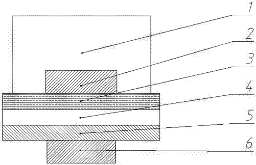
[0020] The pulse width of laser beam 1 described in this example is 10 ns, the highest pulse energy is 0.2 J, and the spot diameter after focusing is 150 μm; the material of mask 2 is copper, the thickness is 0.5 mm, and the shape is a circle with a diameter of 84 μm; the constrained layer 3 is optical glass with a thickness of 0.8 mm; the absorption layer 4 is aluminum foil with a thickness of 50 μm; the metal film 5 is an A304 stainless steel film with a thickness of 100 μm; the material of the lower mold 6 is T7 die steel, and the shape is a cylinder with a diameter of 80 μm .

[0021] After using a laser micro-punching device of the present invention, a large number of A304 stainless steel micro cylinders with a diameter of 80 μm and a height of 100 μm were successfully prepared in large quantities with high dimensional accuracy.

Embodiment 2

[0023] The laser beam 1 described in this example has a pulse width of 10 ns, a maximum pulse energy of 0.3 J, and a spot diameter of 180 μm after focusing; the material of the mask 2 is copper, the thickness is 0.5 mm, and the shape is an equilateral triangle with a side length of 92 μm The constraining layer 3 is transparent resin with a thickness of 0.8 mm; the absorbing layer 4 is black paint with a thickness of 100 μm; the metal film 5 is H62 brass with a thickness of 100 μm; the material of the lower mold 6 is 40Cr die steel, and the shape is side length A triangular prism of 80 μm.

[0024] After using a laser micro-punching device of the present invention, a large number of H62 brass micro-triangular prisms with a diameter of 80 μm and a height of 100 μm were successfully prepared in large quantities with high dimensional accuracy.

Embodiment 3

[0026] The pulse width of the laser beam 1 described in this example is 20ns, the highest pulse energy is 0.8J, and the spot diameter after focusing is 200μm; the material of the mask 2 is copper, the thickness is 0.5mm, the shape is a micro-gear, and the diameter of the indexing circle is 75μm, the number of teeth is 10, and the modulus is 7.5; the constraining layer 3 is transparent resin with a thickness of 1mm; the absorbing layer 4 is black paint with a thickness of 100μm; the metal film 5 is 45 steel with a thickness of 80μm; the material of the lower mold 6 is 20Cr die steel, the shape is a micro-gear, the diameter of the index circle is 60μm, the number of teeth is 10, and the modulus is 6.

[0027] After using a laser micro-punching device of the present invention, a large number of 45 steel micro-gears with high dimensional accuracy, a diameter of 60 μm, a number of teeth of 10, a modulus of 6 and a height of 80 μm were successfully prepared. .


PUM

PropertyMeasurementUnit
thicknessaaaaaaaaaa
thicknessaaaaaaaaaa
thicknessaaaaaaaaaa

Abstract

The invention relates to the field of micro manufacturing, in particular to a micro blanking device based on laser shock. The micro blanking device is characterized in that the upper end face of a lower die is covered with a metal film, an absorbing layer, a restraint layer and a mask in sequence, the mask is exactly opposite to the lower die, and relative positions are guaranteed through a clamp system. The appearance of the mask is similar to that of the lower die. The dimension of the mask is 4-15 microns larger than that of the lower die. One part of high-energy pulse laser light radiates on the surface of the mask and is reflected, and the other part of the high-energy pulse laser light passes through the restraint layer, forms laser spots in specific shapes and radiates on the surface of the absorbing layer. The absorbing layer absorbs laser energy and produces plasma explosion under the restraint of the restraint layer, so shock waves are formed. Under the action of the shock waves having specific outlines and the low die, the part, covered with the mask, of the metal film is reserved, the peripheral part is cut off, and then a flat micro part having a specific shape is obtained.

Description

technical field [0001] The invention relates to the field of micro-manufacturing, in particular to a laser shock micro-punching device. Background technique [0002] With the rapid development of micro-electromechanical systems, the demand for micro-parts is also increasing; currently, the processing technologies for MEMS systems mainly include LIGA, photolithography, etching, micro-extrusion, micro-imprinting, and micro-sheet metal. , micro-drawing, micro-stamping, micro-forging, micro-rolling and micro-die-free forming processes, these processes are limited by problems such as low processing efficiency, high cost, and environmental pollution. [0003] In recent years, with the rapid development of laser technology, laser technology has been widely used in the manufacture of micro-parts. The use of high-power pulsed laser and the mechanical effect of the interaction between materials has attracted more and more attention in the field of material processing. It has been wid...

Claims


Application Information

Patent Timeline
Patent Type & Authority Patents(China)
IPC IPC(8): B21D26/06B23K26/18
Inventor 戴峰泽何鹏
Owner JIANGSU UNIV
Why Eureka
Try Eureka