
Two-chip brushless DC motor drive control system and control method thereof

A brushed DC motor and drive control technology, applied in the field of servo control, can solve the problems of increasing production cost, long response delay, inability to achieve high-precision control of torque and speed, and achieve the effect of reducing system cost and ensuring safe operation.

Active Publication Date: 2015-08-19
OCEAN UNIV OF CHINA
View PDF6 Cites 22 Cited by
  • Summary
  • Abstract
  • Description
  • Claims
  • Application Information

AI Technical Summary

Problems solved by technology

[0003] The speed regulation method of the brushless DC motor is usually realized by open-loop PWM modulation, and the change of the speed is realized through the external given duty ratio, but this speed regulation method is suitable for occasions that do not require high speed regulation, and cannot meet the requirements of relatively high speed. High speed regulation performance requirements, can not achieve high precision control of torque speed
At the same time, the traditional single-chip microcomputer control system, special motor control system and DSP control system, when implementing fault protection, the fault protection circuit realized has a long response delay, which reduces the safety of the system
[0004] The closed-loop speed control and closed-loop position control system of the traditional brushless DC motor needs to use the encoder as a sensor to detect the speed and position of the motor, which increases the production cost of the system when used

Method used


Image

  • Two-chip brushless DC motor drive control system and control method thereof
  • Two-chip brushless DC motor drive control system and control method thereof
  • Two-chip brushless DC motor drive control system and control method thereof

Examples


Embodiment Construction

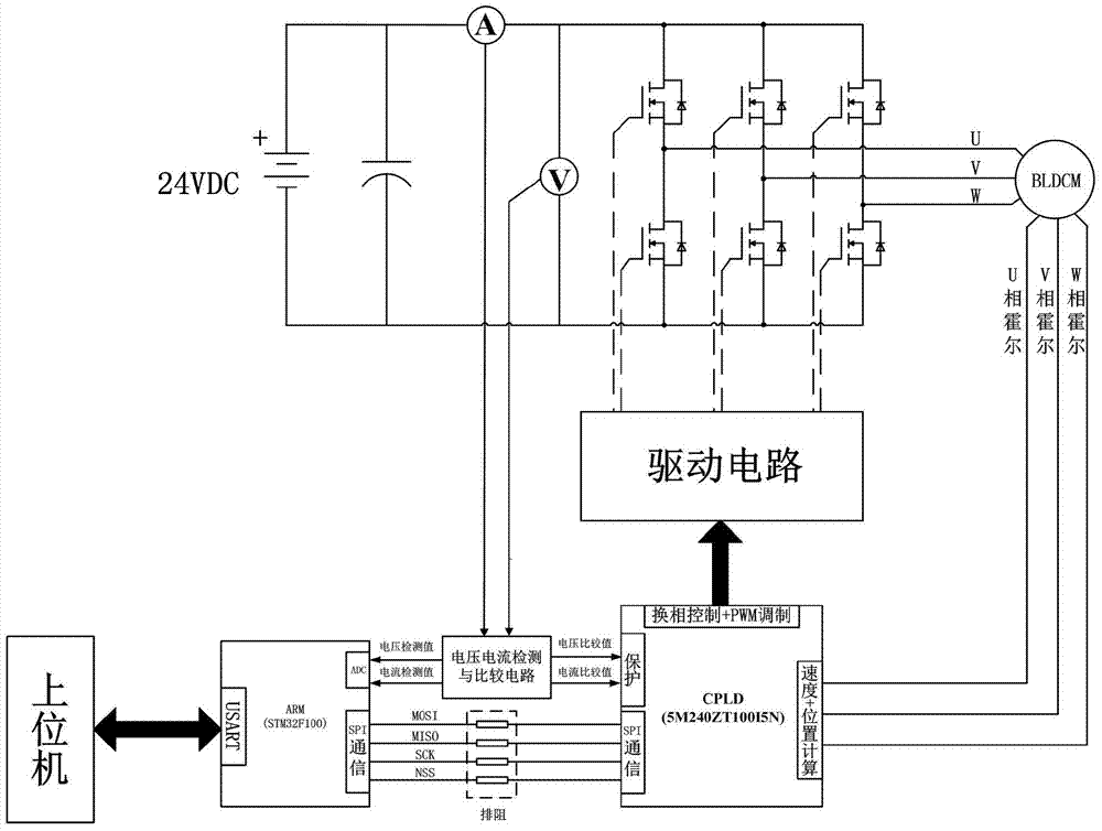
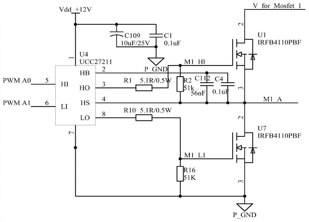
[0049] Such as figure 1 As shown, the brushless DC motor drive control system includes the motor host computer, drive circuit, current detection and comparison circuit, voltage detection and comparison circuit, and control system. The brushless DC motor has a built-in three-phase Hall sensor, and the motor drive circuit is a three-phase phase full bridge circuit.

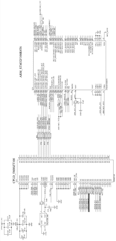
[0050] The control system includes a logical processor connected to each other, a microprocessor, and a drive circuit connected to the logical processor. Such as figure 2 As shown, the logic processor uses a CPLD chip of model 5M240ZT100I5N, and the microprocessor uses an ARM chip of model STM32F100R8T6, and the two communicate through the SPI bus.

[0051] The system does not use position and speed sensors, but uses the position value and speed value of the motor rotor fed back by the Hall sensor inside the brushless DC motor. Since the value fed back by the Hall sensor is not a continuous signal, but only a fixe...


PUM


Abstract

The present invention relates to a drive control system for controlling a brushless motor by using the combination of two chips. According to the system, the e ARM and CPLD combined control is used, the set values of the torque, speed and position of the system are from a host machine, and the feedback value of a motor state is calculated according to the feedback value of a three-phase Hall sensor in the motor. The ARM is connected to the host machine and receives the set values sent by the host machine and carries out torque control, speed control or position control according to the command of the host machine. The CPLD receives feedback signal of the three-phase Hall sensor, carries out position and speed calculation and sends the calculation values to the ARM. The ARM carries out control operation by combining the calculation values and the set values and sends a command word. The CPLD receives the command word of the ARM and parses the command word as a control command, and the motor is controlled to run through the driving circuit of the motor. According to the system, the speed and position sensors are not needed, the system structure is simplified, and the high precision control of the torque, rotation speed and position can be realized.

Description

technical field [0001] The invention belongs to the technical field of servo control, and relates to a brushless motor drive control system and a control method. Background technique [0002] A brushless DC motor consists of a rotor made of permanent magnet material, a stator with coil windings and a position sensor. While it has the superior speed regulation performance of DC motors, it also eliminates various problems caused by carbon brushes and slip ring structures. It also has the advantages of simple structure, high efficiency and reliable operation. [0003] The speed regulation method of the brushless DC motor is usually realized by open-loop PWM modulation, and the change of the speed is realized through the external given duty ratio, but this speed regulation method is suitable for occasions that do not require high speed regulation, and cannot meet the requirements of relatively high speed. High speed regulation performance requirements, it is impossible to achi...

Claims


Application Information

Patent Timeline
IPC IPC(8): H02P6/00H02P6/08H02H7/08
Inventor 黎明王建国张家明陈震张帅
Owner OCEAN UNIV OF CHINA
Learn More