Two-dimensional silicon-based photonic crystal solar battery

A technology of solar cells and photonic crystals, applied in photovoltaic power generation, circuits, electrical components, etc., to achieve the effects of increasing light trapping and light absorption, good light trapping effect, and large specific surface area

Inactive Publication Date: 2015-08-26
QINGDAO UNIV
View PDF2 Cites 5 Cited by
  • Summary
  • Abstract
  • Description
  • Claims
  • Application Information

AI Technical Summary

Problems solved by technology

[0010] The silicon dielectric column (or hole) structure is considered to be one of the solar cell device materials with the most potential for light trapping, but in the existing research, the nanostructures used are mostly one-dimensional structures, and the mechanism used is also to trap light through diffuse reflection. Some studies have proposed a two-dimensional structure of radial silicon nanowires, which has not been combined with the forbidden band and slow light theory of photonic crystal structure

Method used


Image

  • Two-dimensional silicon-based photonic crystal solar battery
  • Two-dimensional silicon-based photonic crystal solar battery
  • Two-dimensional silicon-based photonic crystal solar battery

Examples


Embodiment 1

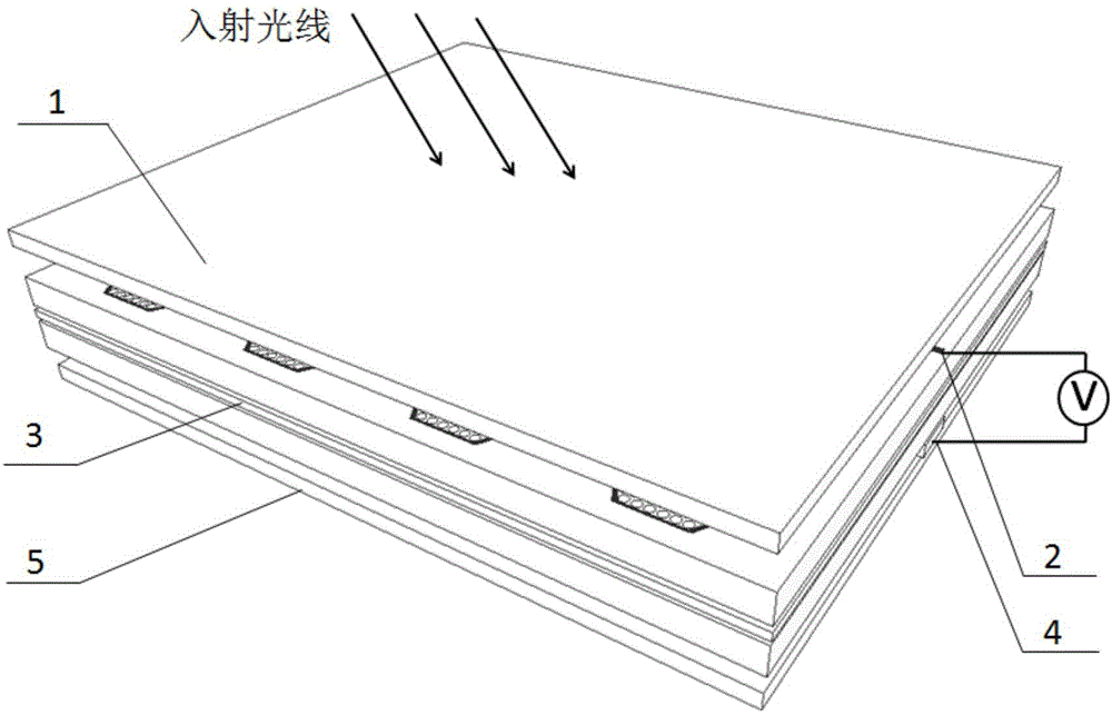
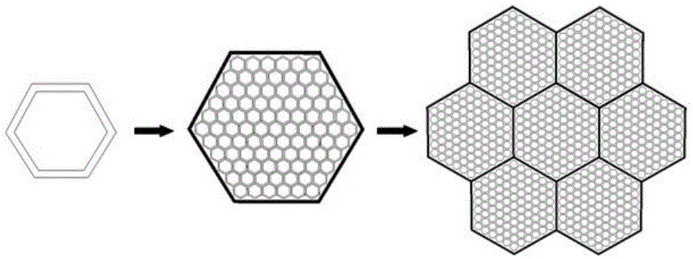
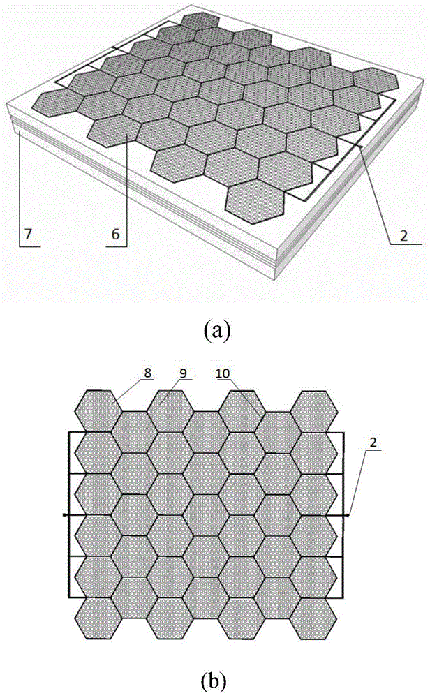
[0037] The honeycomb solar cell structure 3 involved in this embodiment is an air hole structure, and the upper N-type silicon semiconductor layer 6 of the honeycomb solar cell structure 3 is a structure with two substructures of forbidden band and slow light effect arranged periodically. The band building element 8 adopts hexagonal air holes; the spatial arrangement of the honeycomb solar cell structure 3 is a triangular lattice structure, the central wavelength λ=700nm of the forbidden band, and the process of forming the forbidden band building element 8 by the hexagon is as follows figure 2 As shown, the perspective view and top view of the honeycomb solar cell structure 3 are respectively as image 3 (a) and image 3 As shown in (b), according to the existing plane wave expansion method, it can be obtained that the air hole structure has a good band gap for TM mode electromagnetic waves, especially when the parameter β is between 0.37 and 0.53, the relative band gap of T...

Embodiment 2

[0041] The honeycomb solar cell structure 3 involved in this embodiment is a dielectric columnar structure, and the band gap construction element 8 of the N-type silicon semiconductor layer adopts a hexagonal dielectric column; the spatial arrangement of the honeycomb solar cell structure 3 is a triangular lattice structure; The central wavelength λ=700nm of the forbidden band, the three-dimensional view and the top view of the honeycomb solar cell structure 3 are respectively as follows Figure 7 (a) and Figure 7 As shown in (b), it can be obtained by the plane wave expansion method: the dielectric columnar structure has a good band gap for the TE mode electromagnetic wave, especially when the parameter β is between 0.13 and 0.29, the relative band gap of the TE mode exceeds 40%, but The band gap of the TM mode in this area is very small, and the area where the relative band gap of the TM mode exceeds 7% is 0.33-0.47, see respectively Figure 8 (a) and (b), the forbidden ba...


PUM


Abstract

The invention belongs to the field of a solar battery technology, and relates to a two-dimensional silicon-based photonic crystal solar battery. The lower side surface of a front contact layer is provided with a front electrode; a honeycomb-like solar battery structure is arranged between the front electrode and a back electrode, the upper layer of the honeycomb-like solar battery structure is an N-type silicon semiconductor layer, the lower layer of the honeycomb-like solar battery structure is a P-type silicon semiconductor layer, and the N-type silicon semiconductor layer and the p-type silicon semiconductor layer form a PN junction; the bottom of the back electrode is provided with a back contact layer, and the material of the back contact layer is the same as the material of the front contact layer; the back electrode is arranged in a slow light area or a forbidden band area of the P-type silicon semiconductor layer, the shape of the back electrode is the same as the shape of the front electrode, and the front electrode and the back electrode are both strip-shaped; and incident light is irradiated on the honeycomb-like solar battery structure through the front contact layer. The two-dimensional silicon-based photonic crystal solar battery is regular in structure, high in flexibility and changeability and mature in processing and compounding technologies, thereby being a low-cost high-efficiency solar battery device with most potential of a new generation.

Description

Technical field: [0001] The invention belongs to the technical field of solar cells, and relates to a novel photonic crystal solar cell structure, in particular to a honeycomb cluster, hexagonal region division, small thickness, good structural characteristics, relatively wide forbidden band of photons, front electrode A two-dimensional silicon-based photonic crystal solar cell that is embedded along the segmented area, has less shading, has a certain slow light effect, and has high carrier-to-photonic conversion efficiency. Background technique: [0002] As a clean, pollution-free and inexhaustible energy source, solar energy is an important aspect of new energy development. The solar constant published by the World Meteorological Organization is 1367±4W·m -2 , the solar energy that reaches the earth's surface every year and is convenient for human use is about 1.9×10 22 J, these radiations are mainly concentrated in the visible region (400-750nm). Solar energy has been ...

Claims


Application Information

Patent Timeline
Patent Type & Authority Applications(China)
IPC IPC(8): H01L31/0224H01L31/042H01L31/0352
CPCY02E10/50H01L31/022425H01L31/035281H01L31/042
Inventor 万勇孙彬贾明辉孙蕾高竞
Owner QINGDAO UNIV
Why Eureka
Try Eureka