Method and device for testing burning rate of carbonaceous heat source
A technology of carbonaceous heat source and testing method, which is applied in the direction of using combustion for chemical analysis, etc., can solve the problems of lack of evaluation of the combustion rate of carbonaceous heat source, achieve high test efficiency, improve test efficiency, and simple device structure
- Summary
- Abstract
- Description
- Claims
- Application Information
AI Technical Summary
Problems solved by technology
Method used
Image
Examples
Embodiment 1
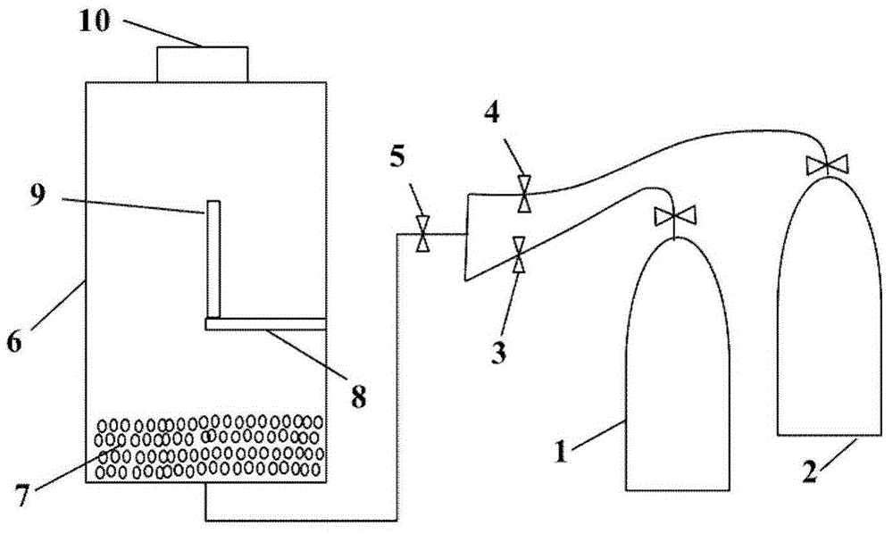
[0023] In this embodiment, the measuring device such as figure 1 shown, which includes:
[0024] A glass container 6 is set, and a layer of 3-5cm thick glass beads 7 is laid on the bottom of the glass container 6, so that the nitrogen-oxygen mixture fed from the bottom flows evenly upwards; on the side of the glass container 6 A spline holder 8 is arranged on the wall to fix the carbonaceous heat source spline 9; the top of the glass container 6 has an opening for discharging the nitrogen-oxygen mixture.
[0025] The diameter of the glass microspheres 7 is 1-2mm. The flow rate of the nitrogen-oxygen mixture is adjusted to 10L / min by the nitrogen-oxygen mixture flowmeter 5; the flow ratio of nitrogen and oxygen in the nitrogen-oxygen mixture is adjusted by the nitrogen gas flowmeter 3 and the oxygen flowmeter 4. The free end of the carbonaceous heat source spline 9 fixed on the spline holder 8 is vertically upward, vertically downward or any angle in the middle.
[0026] The...
Embodiment 2
[0032] Embodiment 2: This embodiment is to investigate the influence of oxygen content on the combustion rate of carbonaceous heat source
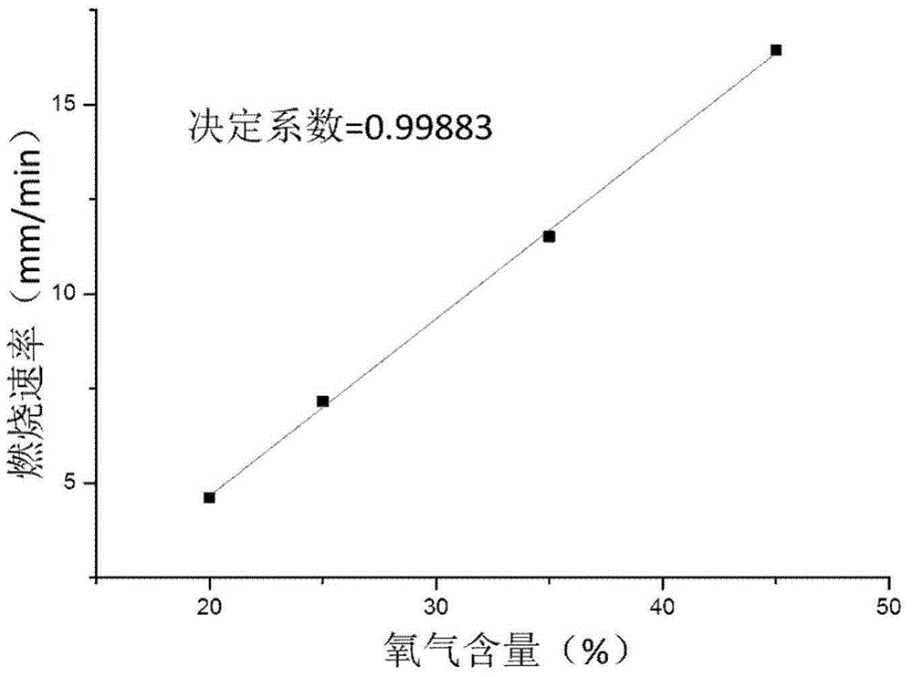
[0033] Utilize the carbonaceous heat source sample bar among the embodiment 1, test method is unchanged, difference is to adjust respectively the oxygen flow rate in the nitrogen-oxygen mixture to be 2.0L / min, 3.5L / min and 4.5L / min, the nitrogen-oxygen mixture The flow rate was kept constant at 10L / min, and the measured combustion rates of the carbonaceous heat source sample were 4.60mm / min, 11.50mm / min, and 16.43mm / min under different oxygen content conditions. The combustion rate tested under the different oxygen content in embodiment 1 and embodiment 2 is plotted to oxygen content, as figure 2 , it can be seen that the coefficient of determination of the fitted linear equation between the two is as high as 0.99883, indicating that the combustion rate of carbonaceous heat sources has a linear dependence on the oxygen content. Therefore...
Embodiment 3
[0034] Embodiment 3: This embodiment is used to evaluate the influence of carbonaceous heat source composition on its combustion rate
[0035] The carbonaceous heat source sample prepared by different carbonaceous heat source formulas is shown in Table 1 under the condition of oxygen concentration of 25% (nitrogen and oxygen flow ratio is 3:1) (see Example 1 for the test method), it can be seen that The addition of potassium chlorate can effectively increase the combustion rate of carbonaceous heat source, while the addition of calcium carbonate, magnesium oxide whiskers and montmorillonite can all reduce the combustion rate of carbonaceous heat source, and the reduction of montmorillonite is as high as 31%. Therefore, the test method for the combustion rate of carbonaceous heat sources provided by the present invention can effectively evaluate the influence of various components on the combustibility of carbonaceous heat sources, and has great guiding significance for the form...
PUM
| Property | Measurement | Unit |
|---|---|---|
| diameter | aaaaa | aaaaa |
Abstract
Description
Claims
Application Information
 - R&D
- Intellectual Property
- Life Sciences
- Materials
- Tech Scout
- Unparalleled Data Quality
- Higher Quality Content
- 60% Fewer Hallucinations
Browse by: Latest US Patents, China's latest patents, Technical Efficacy Thesaurus, Application Domain, Technology Topic, Popular Technical Reports.
© 2025 PatSnap. All rights reserved.Legal|Privacy policy|Modern Slavery Act Transparency Statement|Sitemap|About US| Contact US: help@patsnap.com


