Broadband radiating unit and antenna array

A technology of radiating elements and antenna arrays, which is applied to the structural form of radiating elements, antennas, and devices that enable antennas to work in different bands at the same time. It can solve the problems of complex assembly, poor intermodulation stability, and low gain in high-frequency bands, etc. Simple, high directivity coefficient, the effect of ensuring stability

Active Publication Date: 2015-09-09
WUHAN HONGXIN TELECOMM TECH CO LTD
View PDF12 Cites 32 Cited by
  • Summary
  • Abstract
  • Description
  • Claims
  • Application Information

AI Technical Summary

Problems solved by technology

[0005] In view of the fact that the current broadband radiating unit generally has low gain in the high frequency band, poor cross-polarization ratio, different polarization and co-polarization isolation, and many other problems such as complex assembly and poor intermodulation stability, The present invention proposes a broadband radiation unit, which can obviously overcome the above-mentioned many problems. The antenna array formed by using this radiation unit according to a specific method has good circuit performance and radiation index, simple assembly, high intermodulation stability, and comprehensive performance. Excellent advantage

Method used


Image

  • Broadband radiating unit and antenna array
  • Broadband radiating unit and antenna array
  • Broadband radiating unit and antenna array

Examples


Embodiment Construction

[0025] The technical solutions of the present invention will be described in detail below in conjunction with the accompanying drawings and embodiments.

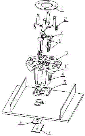
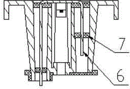
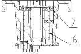
[0026] Such as Figure 1 to Figure 8 As shown, the broadband radiation unit involved in this embodiment includes a support balun 4, a radiation arm 3, a feed core 6, a positioning dielectric block 7, a positioning support buckle 2, a parasitic radiation piece 1, and a vibrator spacer 5. An embodiment provides a dual polarized radiating element, see Figure 6 , the radiating arm 3 has two pairs, the intersections are distributed in a cross shape, located above the supporting balun 4, and the two feed cores 6 are located inside the radiating unit (that is, in the supporting balun 4), to couple and feed the vibrator The supporting balun 4 and the radiation arm 3 constitute the main body of the vibrator, the vibrator spacer 5 is located below the main body of the vibrator (that is, below the supporting balun 4 ), and the parasi...


PUM


Abstract

The invention provides a broadband radiating unit and an antenna array. The broadband radiating unit comprises a support Balun, a radiation arm, a feeding core, a positioning dielectric block, a positioning support snap, a parasitic radiation sheet and an oscillator pad. The radiation arm is above the support Balun, and an oscillator body is formed by the support Balun and the radiation arm. The feeding core is in the cylindrical hole of the support Balun and is coated and positioned by the positioning dielectric block. The oscillator pad is under the oscillator body. The parasitic radiation sheet is fixed above the positioning support snap which is fixed above the radiation arm. In antenna array, a PCB protruding column is arranged under the support Balun of each radiation unit, the PCB protruding column goes through a reflection plate and a PCB and then is welded to a microstrip grounding block, one end of the feeding core is connected to the oscillator body by using the mode of coupling feed, and the other end goes through the reflection plate and the PCB and then is welded to a microstrip line. The radiating unit of the invention has the advantage of simple assembly, few solders, flexible wire running of a back PCB, and higher intermodulation stability.

Description

technical field [0001] The invention relates to the field of mobile communication base station antennas, in particular to a broadband radiation unit suitable for broadband frequency bands and a corresponding antenna array. Background technique [0002] In the cellular mobile communication system, the broadband smart antenna is the main component for radio frequency signal coverage and an important part of the entire mobile transceiver system. The performance of the broadband smart antenna is directly related to the overall performance of the mobile communication network. [0003] The traditional broadband smart antenna radiating unit mainly has the following problems: 1. The gain of the radiating unit in the frequency band above 2.5 GHz is obviously low. For example, the Chinese patent with patent number 201010581310.9 has the above problems. 2. The application occasions are limited, and some occasions with high requirements for intermodulation cannot be satisfied. F...

Claims


Application Information

Patent Timeline
Patent Type & Authority Applications(China)
IPC IPC(8): H01Q1/36H01Q5/392
Inventor 季胜利张申科
Owner WUHAN HONGXIN TELECOMM TECH CO LTD
Why Eureka
Try Eureka