

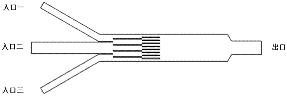
A three-inlet concentration gradient generator and a method for generating a power function concentration gradient
A concentration gradient and generator technology, applied in the application field, can solve problems such as poor versatility, increased requirements for external instruments, complex equipment structure, etc., to achieve the effect of simplified structure and simple and compact overall structure
- Summary
- Abstract
- Description
- Claims
- Application Information
AI Technical Summary
Problems solved by technology
Method used
Image

Examples
preparation example Construction
[0034] The preparation method of the concentration gradient generator is as follows:
[0035](1) Photolithography: Design and draw the micro-channel pattern, and then output the pattern to the film. Using standard photolithography technology, transfer the micro-channel pattern to the silicon substrate template of SU-8 negative photoresist. forming a male mold patterned by microchannels;
[0036] (2) Pattern transfer: Mix the PDMS prepolymer and cross-linking agent evenly according to the mass ratio of 10:1, pour horizontally onto the SU-8 mold obtained by photolithography, put it in a vacuum box for 15 minutes to remove air bubbles, and then put Heat it in an oven at 70°C for 2 hours until it solidifies and take it out. Cut and peel off the PDMS, then use a hole punch to punch holes at the individual inlet and outlet channels;
[0037] (3) Bonding: The PDMS substrate with microstructure and the cleaned and dried glass cover slip are permanently bonded with a plasma machine t...
Embodiment 1
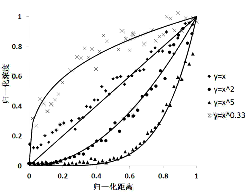
[0039] Example 1: Generation of a linear concentration gradient
[0040] (1) Preparation: prepare 5 mg / L and 2.5 mg / L fluorescein isothiocyanate (FITC) aqueous solutions respectively. Connect the three inlets to the three syringe pumps, and the outlet channel to the waste liquid pool.
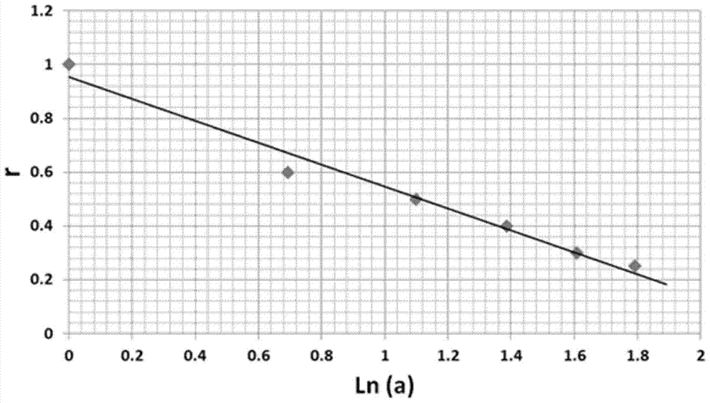
[0041] (2) Operating parameters: inject 5mg / L FITC solution into the first inlet, inject 2.5mg / L FITC solution into the second inlet, and inject deionized water into the third inlet. The flow rate at the second inlet is 20 μm / s. For a concentration gradient generator with a width of 400 μm and a height of 30 μm, the width of the second inlet is 168 μm, and the flow rate of the second inlet can be calculated to be 6.05 nL / min. According to the aforementioned relationship of r=0.95-0.41lna, where a=1, r=0.95 can be obtained, which is approximately 1, that is, the flow rates of the three inlet channels are equal. The widths of inlet 1 and inlet 3 are both 106 μm, and the flow rates of inlet 1 an...
Embodiment 2
[0043] Embodiment 2: y=x 2 Generation of Concentration Gradients
[0044] (1) Preparation: prepare 5 mg / L and 1.25 mg / L fluorescein isothiocyanate (FITC) aqueous solutions respectively. Connect the three inlets to the three syringe pumps, and the outlet channel to the waste liquid pool.
[0045] (2) Operating parameters: inject 5 mg / L FITC solution into the first inlet, inject 1.25 mg / L FITC solution into the second inlet, and inject deionized water into the third inlet. Inlet two flow is still 6.05nL / min. According to the aforementioned relationship of r=0.95-0.41lna, where a=2, r=0.67 can be obtained, that is, the speed of the third entrance is 13.2 μm / s. From this, the flow velocity of inlet one can be obtained as 26.8 μm / s. The widths of the first and third inlets are both 106 μm, and the flow rate of the first inlet is 5.11 nL / min, and the flow rate of the third inlet is 2.52 nL / min.
[0046] (3) Acquisition of results: Place the concentration gradient generator unde...
PUM
 Abstract
Description
Claims
Application Information