
Flue gas treatment system and method thereof

A flue gas treatment and flue gas technology, applied in separation methods, chemical instruments and methods, air quality improvement, etc., can solve the problems of too many equipment, loss of activity, loss of nitrogen oxides, etc., to improve removal efficiency and save money Operating cost and effect of reducing injection volume

Active Publication Date: 2018-09-11
ZHONGJING ENVIRONMENTAL TECH CO LTD
View PDF11 Cites 0 Cited by
  • Summary
  • Abstract
  • Description
  • Claims
  • Application Information

AI Technical Summary

Problems solved by technology

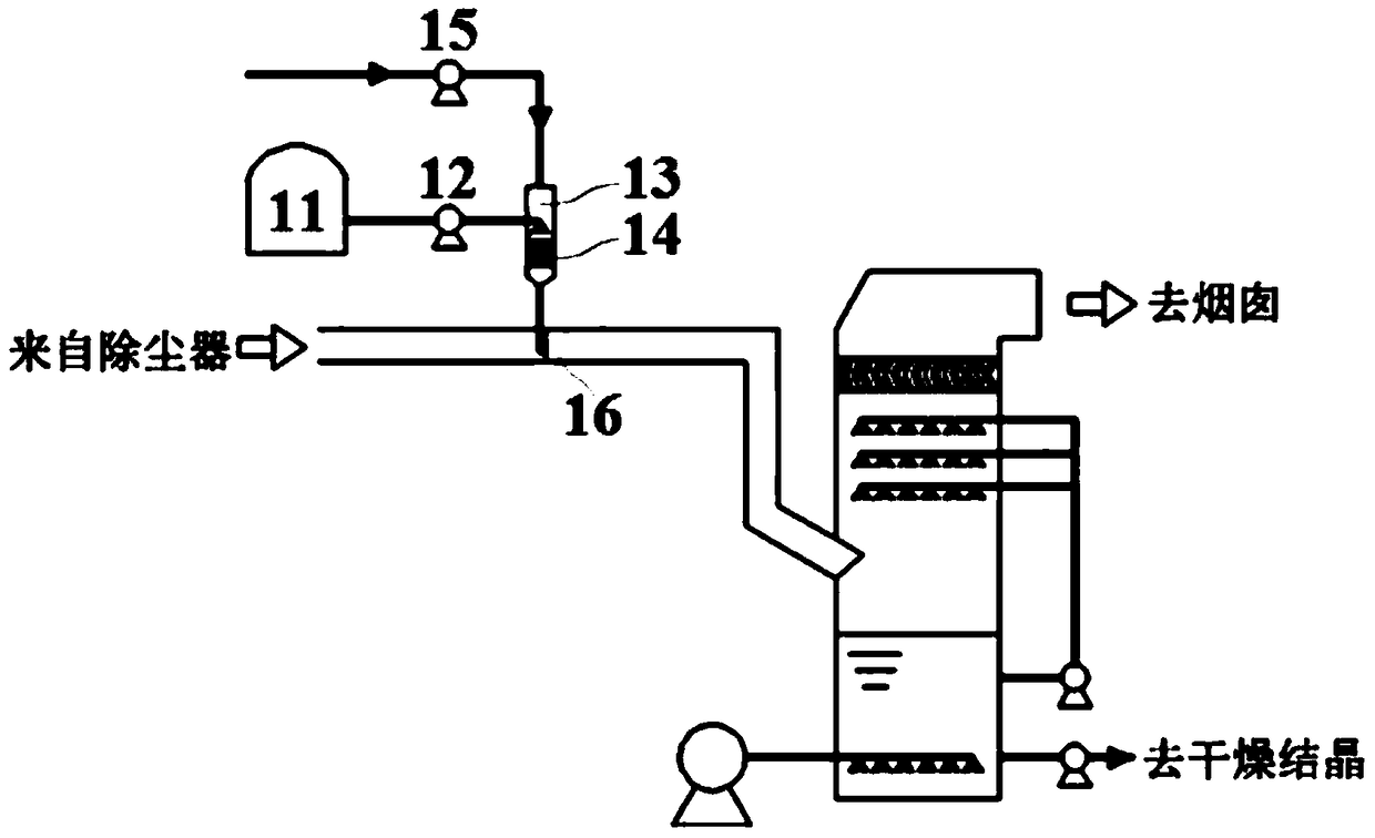
[0003] In terms of desulfurization and denitrification technology, CN102327735A and CN103463978A disclose a H-based 2 o 2 The system and method for simultaneous desulfurization and denitrification of flue gas by catalytic oxidation, these patent documents all adopt the method of injecting H 2 o 2 , this injection method has the following defects: (1) due to the H 2 o 2 It is unstable, and it will decompose ineffectively when it is above 120°C, especially at 140°C and above, and it will decompose strongly into H 2 O and O 2 , losing nitrogen oxides (NO X ), and the flue gas temperature of most of the flue gas in the flue section (before entering the absorption tower) is just within this temperature range
(2) Whether it is the flue gas of the sintering machine in the steel plant or the flue gas of the coal-fired boiler, there is a lot of dust, H 2 o 2 The hydroxyl radical itself and the active substance formed by excitation under certain conditions will undergo instantaneous aggregation when encountering dust, making it inactive and greatly reducing H 2 o 2 Should have strong oxidation properties
(3)H 2 o 2 At 50-70°C, atomized water content is 10%-13%, and the environment water content is 30%-40%, more hydroxyl radicals·OH and·O will be excited. 2 H, while the flue gas temperature at the inlet position is too high and the water content is low, which cannot meet such conditions, resulting in H 2 o 2 Stimulate the active substances hydroxyl radical · OH and · O with substantial oxidation significance 2 The amount of H is greatly reduced
(4) The equipment used for denitrification outside the tower is many and complex, and occupies a large area, which increases investment and operating costs
In addition, the demister installed in the wet desulfurization tower can only remove larger droplets with a particle size greater than 15 μm, while a large number of fine droplets in the flue gas cannot be removed, resulting in a high content of droplets in the exhaust gas
[0006] To sum up, there is currently no feasible method for desulfurization, denitrification, mercury removal, dust removal and fog removal for flue gas at the same time.

Method used


Image

  • Flue gas treatment system and method thereof
  • Flue gas treatment system and method thereof
  • Flue gas treatment system and method thereof

Examples


Embodiment 1

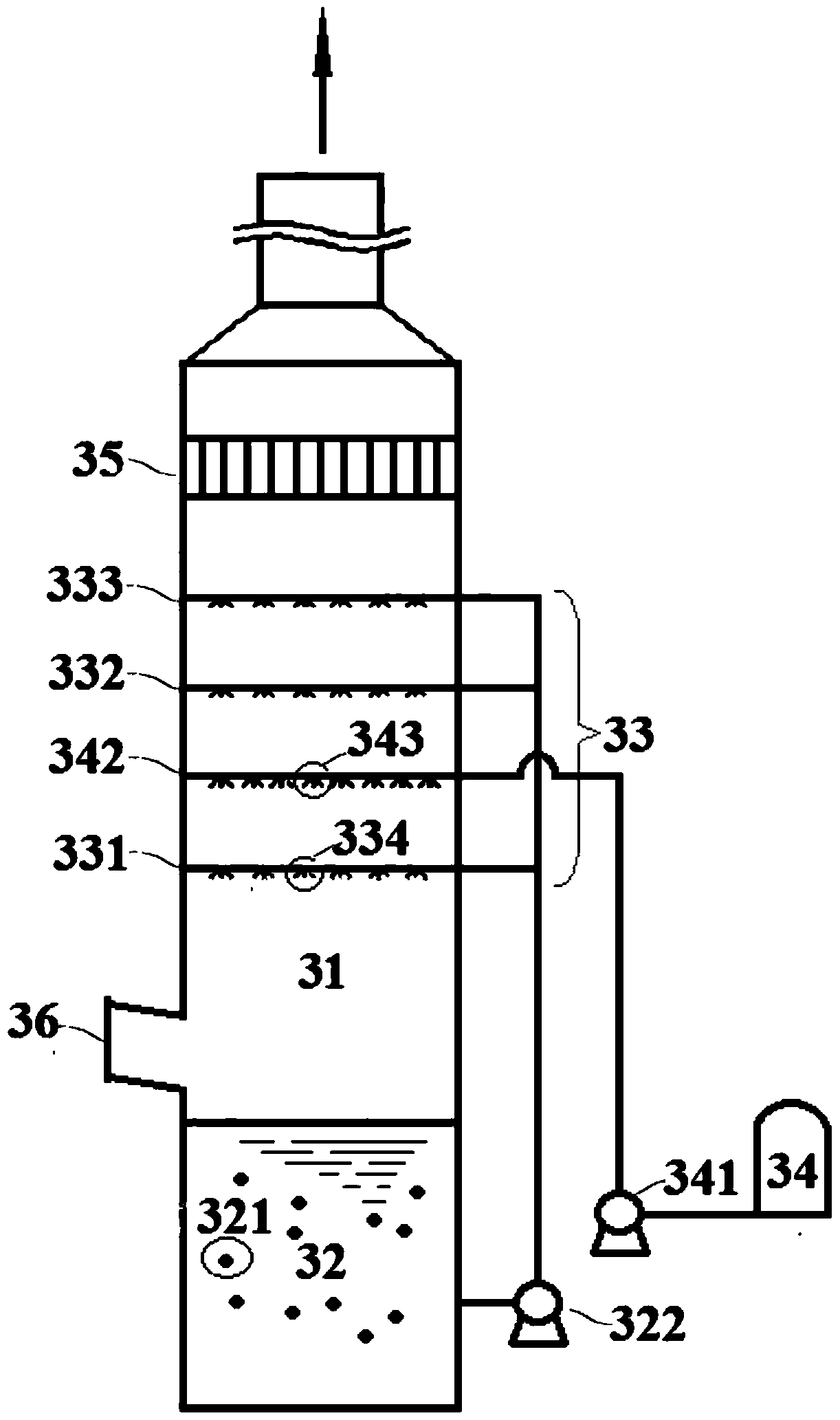
[0126] image 3 A schematic diagram of the system of Embodiment 1 of the present invention is shown. It can be seen from the figure that the flue gas treatment system of the present invention includes a flue gas treatment tower 31 , a hydrogen peroxide storage tank 34 and a rotary dust and mist eliminator 35 . The flue gas treatment tower 31 includes a hydrogen peroxide spray oxidation reaction layer 342, an absorption spray area 33 and a slurry circulation pool 32, wherein the hydrogen peroxide spray oxidation reaction layer 342 is arranged in the absorption spray area 33; The device 35 is located above the absorption spray area 33 . The absorption spray area 33 includes a first absorption spray layer 331 , a second absorption spray layer 332 and a third absorption spray layer 333 . The hydrogen peroxide spray oxidation reaction layer 342 is located between the first absorption spray layer 331 and the second absorption spray layer 332 . The distance between the first absor...


PUM


Abstract

The invention discloses a flue gas treatment system and method. The system comprises flue gas treatment equipment, hydrogen peroxide supply equipment, dedusting and defogging equipment and the like, wherein the flue gas treatment equipment comprises a hydrogen peroxide spray oxidation reaction layer, an absorbing sprinkling area and a slurry circulating area; the hydrogen peroxide spray oxidation reaction layer is arranged in the absorbing sprinkling area; the dedusting and defogging equipment is positioned above the absorbing sprinkling area. The system and the method provided by the invention are suitable for comprehensive treatment of flue gas which contains SO2, NOX, Hg<0> and dust, and is produced by coal burning boilers, steel sintering machines, pellets, industrial furnaces and the like.

Description

technical field [0001] The invention relates to a flue gas treatment system and method thereof, in particular to a system and method for simultaneously removing sulfur dioxide, nitrogen oxides, elemental mercury and dust in flue gas. Background technique [0002] At present, the desulfurization and denitrification technologies commonly used in my country are wet flue gas desulfurization technology (WFGD) (among which calcium method is the majority) combined with selective catalytic reduction denitrification technology (SCR) or selective non-catalytic reduction denitrification technology (SNCR). Recently, some experts proposed to combine the original wet desulfurization device to reuse H 2 o 2 The strong oxidizing property completes desulfurization and denitrification at the same time. The existing mercury removal technology uses a halogen oxidant solution to circulate and spray the raw flue gas, and the elemental mercury (Hg 0 ) after fully oxidized, the gas phase divalen...

Claims


Application Information

Patent Timeline
Patent Type & Authority Patents(China)
IPC IPC(8): B01D53/75B01D53/60B01D53/64B01D50/00
CPCY02A50/20
Inventor 童裳慧
Owner ZHONGJING ENVIRONMENTAL TECH CO LTD
Learn More