Swirl-flow type gasification furnace and swirl-flow type gasification process

A gasification furnace and swirling flow technology, applied in the field of coal chemical industry, can solve the problems of large one-time investment and complicated design, and achieve the effects of high gasification efficiency, convenient operation and excellent technical effect

Inactive Publication Date: 2015-11-11
北京柯林斯达科技发展有限公司
View PDF9 Cites 8 Cited by
  • Summary
  • Abstract
  • Description
  • Claims
  • Application Information

AI Technical Summary

Problems solved by technology

The above-mentioned gasification technologies are all gas heads required by large-scale gas production projects, and the design is complex, the one-time investment is large, and there are certain problems in different degrees

Method used


Image

  • Swirl-flow type gasification furnace and swirl-flow type gasification process
  • Swirl-flow type gasification furnace and swirl-flow type gasification process

Examples


Embodiment 1

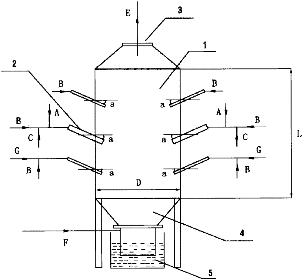
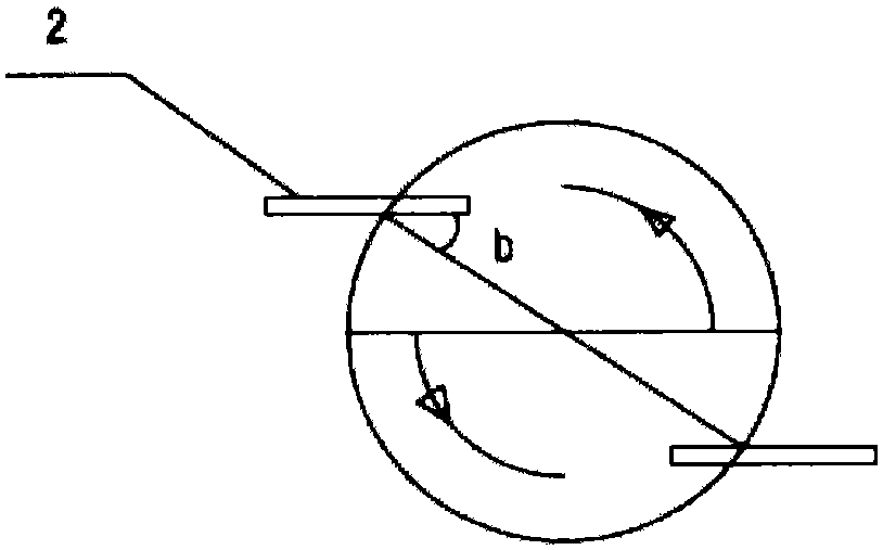
[0036] A swirling flow gasifier, comprising a furnace body 1, a feed lance 2, a gasification gas outlet 3 positioned at the top of the furnace body, and a slag chamber 4 positioned at the bottom of the furnace body; the outer wall of the furnace body 1 adopts Carbon steel, the interlayer is thermal insulation fiber cotton, the inner layer is refractory castable, the length-to-diameter ratio of the furnace body is 1:1; the feed spray gun 2 is arranged in the middle of the furnace body 1, and the feed spray gun is set as Layer layout, the number of feed spray guns in each layer is two, and the two feed spray guns in each layer are arranged symmetrically along the circumference of the furnace body, and the feeding method of the spray guns is tangential feeding; The angle is 50°, and the spray gun is inclined downward at 0°; the feed spray gun arranged in a single layer is the first spray gun, which is used for feeding gasification raw materials and gasification agents, and the fir...

Embodiment 2

[0038] A swirling flow gasifier, comprising a furnace body 1, a feed lance 2, a gasification gas outlet 3 positioned at the top of the furnace body, and a slag chamber 4 positioned at the bottom of the furnace body; the outer wall of the furnace body 1 adopts Stainless steel material, the interlayer is thermal insulation fiber cotton, the inner layer is refractory castable, the aspect ratio of the furnace body is 2:1; the feed spray gun 2 is arranged in the middle of the furnace body 1, and the feed spray gun is set as two Layer layout; the number of feed spray guns in each layer is two, and the two feed spray guns in each layer are arranged symmetrically along the circumference of the furnace body, and the feeding method of the spray guns is tangential feeding; The angle is 35°, and the spray gun is tilted down by 30°; the slag chamber 4 is provided with a pure oxygen injection lance to replenish pure oxygen to maintain a higher temperature in the slag chamber and realize liqu...

Embodiment 3

[0040]A swirling flow gasifier, comprising a furnace body 1, a feed lance 2, a gasification gas outlet 3 positioned at the top of the furnace body, and a slag chamber 4 positioned at the bottom of the furnace body; the outer wall of the furnace body 1 adopts Stainless steel material, the interlayer is thermal insulation fiber cotton, the inner layer is refractory castable, the length-to-diameter ratio of the furnace body is 2:1; Layer layout; the number of feed spray guns in each layer is two, and the two feed spray guns in each layer are arranged symmetrically along the circumference of the furnace body, and the feeding method of the spray guns is tangential feeding; The angle is 45°, and the spray gun is tilted down by 10°; the slag chamber 4 is equipped with a pure oxygen spray gun to supplement pure oxygen to maintain a higher temperature in the slag chamber and realize liquid slag discharge; the lower part of the slag chamber is provided with a slag pool 5. The slag pool ...


PUM


Abstract

The invention discloses a swirl-flow type gasification furnace and swirl-flow type gasification process. The swirl-flow type gasification furnace comprises a furnace body (1), a feeding spray gun (2), a hot coal gas outlet (3) located at the top part of the furnace body, and a slag-melting chamber (4) located at the bottom part of the furnace body. According to the invention, the feeding spray gun used for entering the gasification furnace adopts tangent feeding, and the spray gun slopes down with a certain angle, so gasification raw materials are gasified in a swirl-flow form in the furnace; relative speeds of gas and solid phases are enhanced; retention time is prolonged; and gasification intensity and carbon transformation rate of the gasification furnace are improved; meanwhile, multi-layer spray-gun feeding is adopted, so classified supply of a gasifying agent is realized; reaction of the gasification raw materials and the gasifying agent in the gasification furnace is more fully; and gasification efficiency is higher.

Description

technical field [0001] The invention belongs to the field of coal chemical industry, and in particular relates to a swirl gasifier and a swirl gasification process. Background technique [0002] my country's energy structure is "rich in coal, poor in oil and low in gas". Under this energy structure, coal undoubtedly dominates the energy field. my country is also the country with the largest coal mining and consumption in the world. Behind the massive development and utilization of coal lies huge environmental, social and economic costs. Every step in the coal use process, from mining to burning, causes environmental damage. Especially coal combustion, according to incomplete statistics, 85% of my country's sulfur dioxide emissions, 67% of nitrogen oxide emissions and 70% of suspended particulate matter come from coal combustion. Based on this national situation, and the coal industry policy issued by the National Development and Reform Commission, it is mentioned that the...

Claims


Application Information

Patent Timeline
Patent Type & Authority Applications(China)
IPC IPC(8): C10J3/48C10J3/50
CPCY02E20/18
Inventor 不公告发明人
Owner 北京柯林斯达科技发展有限公司
Why Eureka
Try Eureka