
Laser-assisted liquid metal synchronously-casting mould-free forming method

A liquid metal, laser-assisted technology, applied in the field of additive manufacturing, can solve the problems of reducing the thickness of the simultaneous casting and rolling space, reducing the surface tension of the melt, and affecting the processing efficiency, so as to improve the interlayer bonding force and grain refinement High degree of effect of reducing remelting time

Active Publication Date: 2015-11-18
广东空天科技研究院
View PDF8 Cites 3 Cited by
  • Summary
  • Abstract
  • Description
  • Claims
  • Application Information

AI Technical Summary

Problems solved by technology

The difficulty in solving the latter problem is that metal is a good conductor of heat, and the process window for remelting the previous layer of solidified surface layer is not large only by relying on the heat carried by the subsequent melt, and this process window will also increase with the thermal conductivity of the metal. increase and narrow
[0007] In addition, increasing the temperature of the subsequent melt has some negative effects
For example, to reduce the surface tension of the melt, the thickness of the simultaneous casting and rolling space has to be reduced to prevent the melt from overflowing, thereby affecting the processing efficiency
Another example is to make the solidified structure grow due to overheating, thereby reducing the fine-grain strengthening effect of the molded part

Method used


Image

  • Laser-assisted liquid metal synchronously-casting mould-free forming method
  • Laser-assisted liquid metal synchronously-casting mould-free forming method
  • Laser-assisted liquid metal synchronously-casting mould-free forming method

Examples


Embodiment

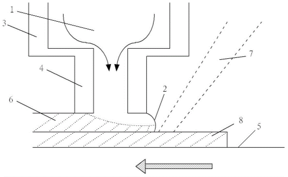
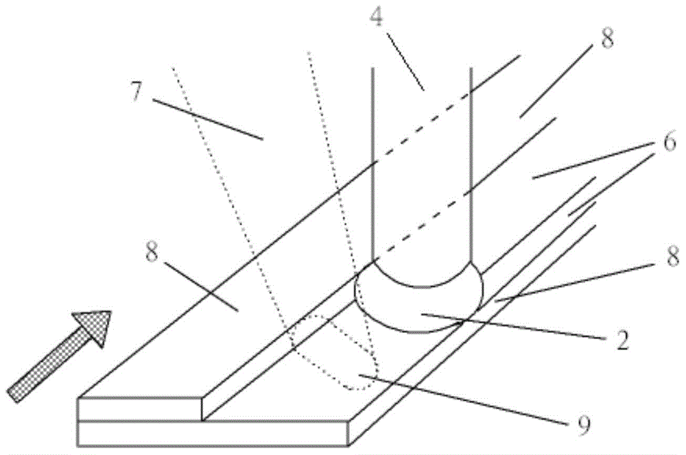
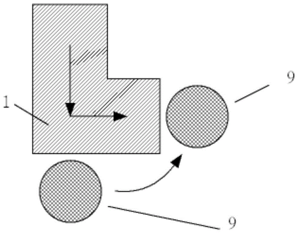
[0042] Example: such as Figure 1-3 as shown,

[0043] (1) Pour the refined tin-lead alloy (Sn-15Pb) into the crucible 3 kept at 230°C. The crucible 3 is provided with a rotatable impeller, and its rotating speed is set at 800rpm to stir the tin-lead alloy melt. The bottom of the crucible 3 There is an outlet with an inner diameter of 1 mm, and below the outlet 4 of the crucible is a substrate 5 that can move in three dimensions, and the distance between the substrate 5 and the bottom end of the outlet 4 of the crucible is not greater than 1 mm;

[0044] (2) Aim at the movement front area 9 that the tin-lead alloy melt will cover with a YAG laser;

[0045] (3) Set in the control software that the laser light emitting time and closing time are synchronized with the time when the substrate 5 starts moving and stops moving, turn on the laser power supply, adjust the laser parameters, and prepare for light emitting;

[0046] (4) Turn on the motion switch, the tin-lead alloy melt...


PUM

PropertyMeasurementUnit
Wavelengthaaaaaaaaaa

Abstract

The invention relates to a laser-assisted liquid metal synchronously-casting mould-free forming method. The laser-assisted liquid metal synchronously-casting mould-free forming method comprises the steps that (1) a laser device is made to aim at a movement front area to be covered with a melt, the time when the laser device is started and the time when the laser device is stopped are set to be synchronous with the time when a base plate starts to move and the time when the base plate stops moving in control software, a laser device power source is started, the parameters of the laser device are adjusted, and the preparation is made for light emitting; (2) a movement switch is turned on, the melt is squeezed out of a crucible under pressure and falls onto the base plate below an outlet of the crucible, and laser light is irradiated onto the movement front area, of the melt, on the base plate at the same time; and (3) forming is ended, the movement switch is turned off, pressurizing of the melt in the crucible is stopped, the melt stops flowing, and laser light irradiation is stopped at the same time. According to metal formed through cast rolling according to the method, the fineness of grains is high, and the compact degree approximates to or reaches the rolling level or the forging level; meanwhile, metallurgical bonding of interlayer interfaces can be well achieved, and the quality of formed products is high.

Description

technical field [0001] The invention belongs to the field of additive manufacturing, and in particular relates to a laser-assisted liquid metal synchronous casting-rolling dieless forming method. Background technique [0002] Additive Manufacturing (Additive Manufacturing, referred to as AM) is a direct manufacturing method based on three-dimensional CAD model data by adding materials layer by layer, and is a manufacturing method for a three-dimensional physical model that is completely consistent with the corresponding mathematical model. [0003] Chinese patent CN201310139419 discloses a mobile micro-die-casting molding method for metal components. The method uses a melt that meets the composition requirements as a raw material, and molds the metal component through a point-by-point layer-by-layer synchronous casting and rolling manufacturing method. [0004] Its specific working principle is: carry out layering and track design on the three-dimensional graphics of metal c...

Claims


Application Information

Patent Timeline
IPC IPC(8): B22D17/00B33Y10/00B33Y40/00
Inventor 李正阳陈光南王红才彭青罗耕星张坤肖京华
Owner 广东空天科技研究院
Learn More