An energy-saving closed cooling tower
A technology of closed cooling tower and cooling unit, which is applied in the direction of water shower cooler, direct contact heat exchanger, heat exchanger type, etc., which can solve the problems of shortening equipment life, shortening the maintenance cycle of heat exchanger, waste of head energy, etc. problems, to achieve the effect of improving cooling heat transfer effect, heat transfer effect, saving water and electricity, and improving heat transfer capacity
- Summary
- Abstract
- Description
- Claims
- Application Information
AI Technical Summary
Problems solved by technology
Method used
Image
Examples
Embodiment 1
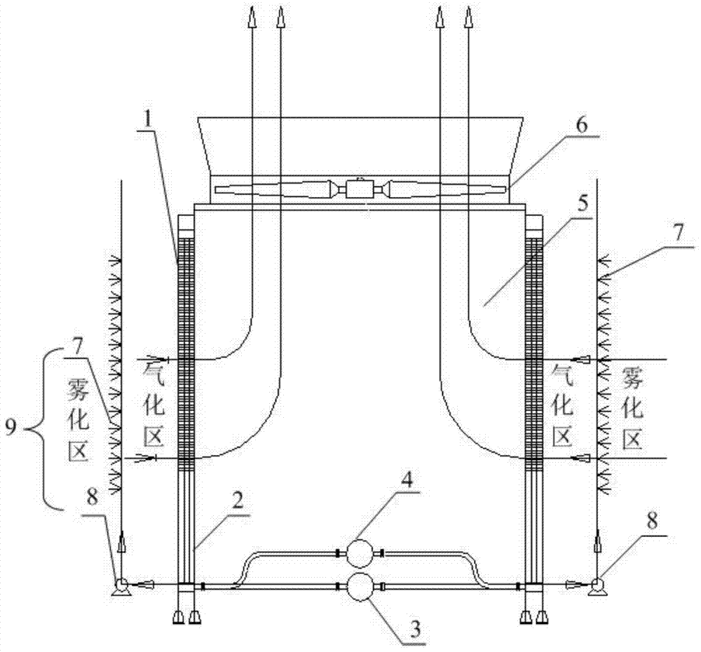
[0034] figure 2 It is a schematic structural diagram of a square energy-saving closed cooling tower provided by Embodiment 1 of the present invention. The energy-saving closed cooling tower includes a box body 5, a heat exchanger installed in the box body 5, a cooling system for cooling the heat exchanger, an air induction device 6 installed on the top of the box body 5, and a The water tank 2 at the bottom of 5, the box 5 is a square box; the cooling system is a high-pressure micro-mist cooling system 9, and the high-pressure micro-mist cooling system 9 is located outside the heat exchanger; the heat exchanger is 2 Two two-phase thermosiphon heat exchangers 1, the start-up temperature of which is ≤40°C, the two two-phase thermosiphon heat exchangers 1 are installed on both sides of the square box; the two two-phase thermosiphon heat exchangers The heat pipe evaporation section of the device 1 is installed inside the water tank 2.
[0035] The high-pressure micro-mist cooli...
Embodiment 2
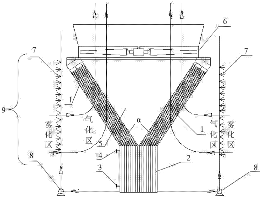
[0042] image 3 It is a schematic structural diagram of a V-shaped energy-saving closed cooling tower provided by Embodiment 2 of the present invention. The V-shaped energy-saving closed cooling tower includes: a box body 5, a heat exchanger installed in the box body 5, a cooling system for cooling the heat exchanger, an air induction device 6 installed on the top of the box body 5, and an installation The water tank 2 at the bottom of the box 5, the box 5 is a V-shaped box; the cooling system is a high-pressure micro-mist cooling system 9, and the high-pressure micro-mist cooling system 9 is located outside the heat exchanger; The heat exchanger is two two-phase thermosiphon heat exchangers 1, and its start-up temperature is ≤40°C; each two-phase thermosiphon heat exchanger 1 is composed of 6 heat pipe bundles, and the height of the heat pipe bundles is 1-25m, such as 2m, 6m, 12m, 17m, 22m, etc., preferably 4m high, 0.1-3m wide, such as 0.2m, 1m, 1.2m, 2.3m, etc., preferably...
Embodiment 3
[0049] Figure 4 It is a schematic top view structure diagram of the energy-saving closed cooling tower combination equipment provided by Embodiment 3 of the present invention. The energy-saving closed cooling tower combined equipment has 3 cooling units, the cooling unit is the square closed cooling tower described in Embodiment 1, and the 3 cooling units are arranged in a straight line; the energy-saving closed cooling tower combined equipment It is rectangular, 12m long, 3m wide and 4.7m high. The cooling unit is a square with a side length (S) of 3m, and each cooling unit is provided with an independent two-phase thermosiphon heat exchanger 1, a high-pressure micro-mist cooling system 9, an air induction device 6 and a water tank 2; and the The two-phase thermosiphon heat exchangers 1 of the three cooling units are connected in series through pipes; the tops of the box body 5 of the three cooling units are respectively equipped with an induced draft fan with a diameter of...
PUM
 Abstract
Description
Claims
Application Information
 - R&D
- Intellectual Property
- Life Sciences
- Materials
- Tech Scout
- Unparalleled Data Quality
- Higher Quality Content
- 60% Fewer Hallucinations
Browse by: Latest US Patents, China's latest patents, Technical Efficacy Thesaurus, Application Domain, Technology Topic, Popular Technical Reports.
© 2025 PatSnap. All rights reserved.Legal|Privacy policy|Modern Slavery Act Transparency Statement|Sitemap|About US| Contact US: help@patsnap.com


