Multiple-back-strip frequency band expanding low-profile double-layer printed ultra-wideband antenna

An ultra-wideband antenna, low-profile technology, applied to antennas, devices that make the antenna work in different bands at the same time, and the structure of radiating elements, etc. Simple processing and the effect of increasing the degree of freedom

Active Publication Date: 2015-12-23
BEIHANG UNIV
View PDF2 Cites 4 Cited by
  • Summary
  • Abstract
  • Description
  • Claims
  • Application Information

AI Technical Summary

Problems solved by technology

Some new ultra-broadband antennas, such as vibrator antennas with reflectors, have good performance, but their profiles are generally h

Method used


Image

  • Multiple-back-strip frequency band expanding low-profile double-layer printed ultra-wideband antenna
  • Multiple-back-strip frequency band expanding low-profile double-layer printed ultra-wideband antenna
  • Multiple-back-strip frequency band expanding low-profile double-layer printed ultra-wideband antenna

Examples


Embodiment 1

[0059] Low-profile double-layer printed UWB antenna structure with single backstrip:

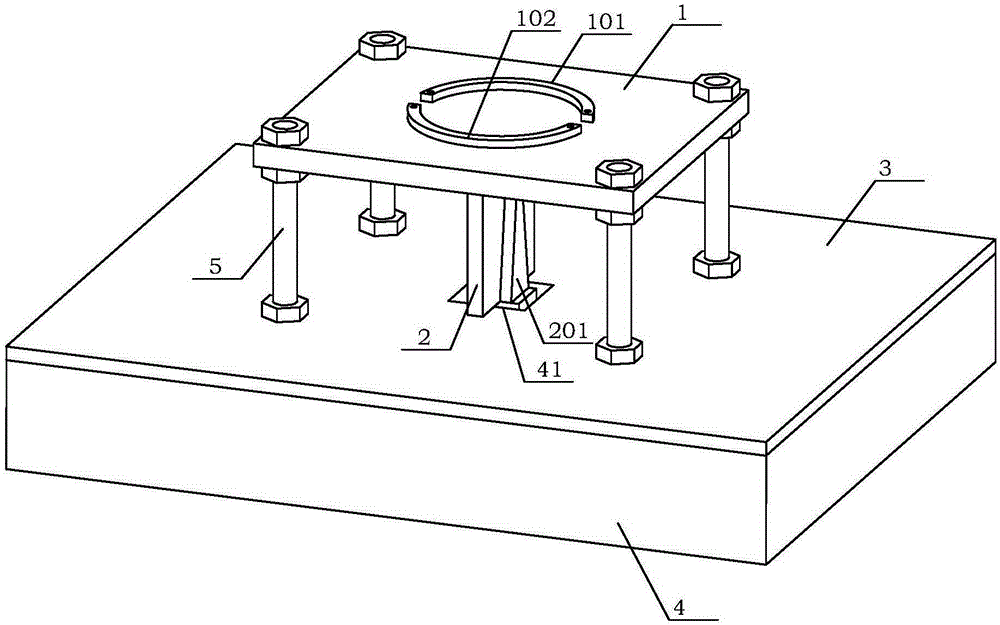
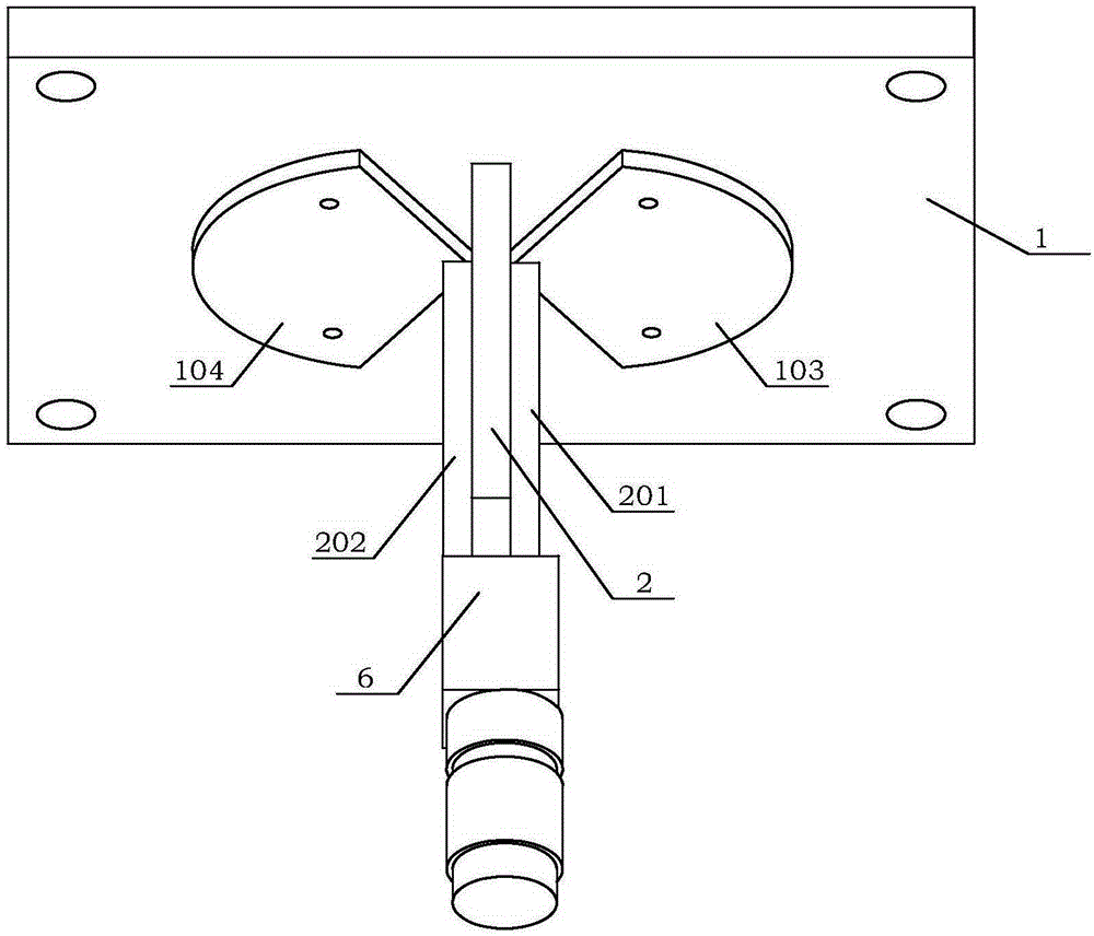
[0060] see figure 2 , Figure 2A , Figure 2B As shown, AA back strips 1A1 are processed on the upper surface 11 of the transverse dielectric board 1 using the copper-clad technology, and the first vibrator 121 and the The second vibrator 122 .

[0061] Horizontal media board 1:

[0062] see figure 1 , Figure 1A , Figure 1B , figure 2 , Figure 2A As shown, the transverse dielectric plate 1 is a rectangular structure, the length of the transverse dielectric plate 1 is denoted as E, and the width is denoted as D, and .

[0063] The upper surface 11 of the transverse dielectric board 1 is provided with an arc-shaped groove having the same configuration as the AA back strip 1A1 , and the arc-shaped groove is coated with copper material using copper cladding technology to form the AA back strip 1A1 . The structure of setting arc-shaped grooves on the upper surface 11 of the trans...

Embodiment 2

[0083] Low-profile double-layer printed ultra-wideband antenna structure with double backstrips:

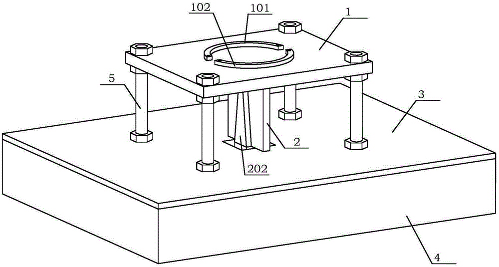
[0084] see image 3 , Figure 3A , Figure 3B As shown, BA back strips 1B1 and BB back strips 1B2 are processed on the upper board surface 11 of the transverse dielectric board 1 using copper-clad technology, and the same structure is processed on the lower board surface 12 of the transverse dielectric board 1 using copper-clad technology. The first vibrator 121 and the second vibrator 122 .

[0085] Horizontal media board 1:

[0086] see figure 1 , Figure 1A , Figure 1B , image 3 , Figure 3A As shown, the transverse dielectric plate 1 is a rectangular structure, the length of the transverse dielectric plate 1 is denoted as E, and the width is denoted as D, and

[0087] The upper plate surface 11 of the transverse dielectric plate 1 is provided with a BA arc-shaped groove having the same configuration as the BA back bar 1B1 and a BB arc-shaped groove having the sam...

Embodiment 3

[0109] Low-profile double-layer printed UWB antenna structure with three back strips:

[0110] see Figure 4 , Figure 4A , Figure 4B As shown, CA back strips 1C1, CB back strips 1C2, and CC back strips 1C3 are processed on the upper board surface 11 of the transverse dielectric board 1 using copper clad technology, and copper clad technology is used on the lower board surface 12 of the transverse dielectric board 1 A first vibrator 121 and a second vibrator 122 with the same structure are processed.

[0111] Horizontal media board 1:

[0112] see figure 1 , Figure 1A , Figure 1B , Figure 4 , Figure 4A As shown, the transverse dielectric plate 1 is a rectangular structure, the length of the transverse dielectric plate 1 is denoted as E, and the width is denoted as D, and

[0113] The upper plate surface 11 of the transverse medium plate 1 is provided with a CA arc-shaped groove having the same configuration as the CA back strip 1C1, a CB arc-shaped groove havin...


PUM

PropertyMeasurementUnit
Gainaaaaaaaaaa
Gainaaaaaaaaaa
Gainaaaaaaaaaa

Abstract

The invention discloses a multiple-back-strip frequency band expanding low-profile double-layer printed ultra-wideband antenna, which is used for adjusting performances of an ultra-wideband antenna such as working waveband, antenna gain and antenna directionality through changing relative positions of the back strips and a vibrator and coupling the back strips with the vibrator to generate induction capacitance. The multiple back strips and the vibrator which are arranged on and under a dielectric plate do not need to be perforated, and a plurality of resonance points are formed by the induction capacitance generated through electromagnetic coupling, thus impedance characteristics of the antenna is reduced along with variation of frequency and the frequency band of the antenna is expanded. The low-profile double-layer printed ultra-wideband antenna is provided with 1 to 3 back strips which respectively expand 3 frequency bands of the original dipole antenna, the equivalent arc length of the back strips is half of wavelength corresponding to center frequency of the frequency band expanding part, thus the antenna covers all communication wireless system services which are commonly used at present, has the advantages of high gain, stable directivity and miniaturization, and has a wide application range in wireless communication.

Description

technical field [0001] The present invention relates to a miniaturized dipole antenna suitable for an ultra-wideband system, more specifically, a dipole antenna capable of adjusting the working band, antenna gain, Low-profile double-layer printed antenna with antenna directivity and other properties. The structure of this patent application is an improvement on the application number CN201210050530.8. Background technique [0002] In the 1980s, with the advancement of electronic science and technology, the frequency bands of radio systems such as communications and radar became wider and wider, the signal pulses became narrower and narrower, and the electromagnetic spectrum became more and more crowded. People began to pay attention to and study ultra-wideband (UWB) Electromagnetism. Around 1990, people used various time-domain numerical methods to obtain the strict transient solutions of Maxwell equations, thus laying a solid theoretical foundation for ultra-wideband elec...

Claims


Application Information

Patent Timeline
IPC IPC(8): H01Q1/38H01Q5/10H01Q5/40H01Q19/10
Inventor 吴琦郭双苏东林
Owner BEIHANG UNIV
Why Eureka
Try Eureka