Electric control hydraulic driving system for industrial vehicle

An electronically controlled hydraulic and drive system technology, applied in electric brake systems, fluid pressure actuation system components, control/regulation systems, etc., can solve problems such as component damage, increased cost and energy consumption, and affect loading and unloading efficiency. Achieve the effect of realizing kinetic energy recovery and potential energy recovery, improving discharge capacity efficiency, and avoiding loss of throttling and speed regulation

Active Publication Date: 2015-12-30
上海市闸北区物流工程技术研究所
View PDF9 Cites 16 Cited by
  • Summary
  • Abstract
  • Description
  • Claims
  • Application Information

AI Technical Summary

Problems solved by technology

[0003] 1) The starting current is large; when the vehicle is frequently moving forward and backward, the current and energy consumption of the motor during braking and starting is large;
[0004] 2) Large climbing current (requires 2 to 3 times the rated current);
[0005] 3) AC motors have defects such as low power factor, low efficiency at low speed, and narrow high-efficiency zone of the motor;
[0006] 4) The cost of imported control drives is high;
[0008] 6) Multiple motors start and run repeatedly at the same time, resulting in superimposed starting and running high currents, which reduces the discharge current capacity of the lead-acid battery by 40%, resulting in increased operating costs, prolonged charging time, and reduced vehicle loading and unloading efficiency;
[0009] 7) Ordinary electric forklifts control the descending speed of the goods through the throttling of the valve when the goods are dropped. The deterioration of the oil will affect the reliability and working efficiency of the hydraulic components, and at the same time, the cost of use will increase due to the need to replace the hydraulic oil;
[0012] 1) When the running mechanism is running at full speed, the mechanical efficiency drops by 18%;
[0013]2) The operation is complicated, which affects the loading and unloading efficiency;
[0014] 3) The lifting mechanism cannot be electronically controlled for speed regulation, and there is throttling loss;
[0016] 5) Brake mechanism and hydraulic motor back pressure loss is serious
[0019] 2) Two hydraulically controlled one-way valves are installed in the walking system, which makes the system complex and increases cost and energy consumption;
[0020] 3) Since there is no speed limit for sliding slopes in the walking mechanism, it will cause speeding and bring mental burden and danger to the operator;
[0021] 4) Lack of oil replenishment mechanism when the vehicle brakes and slides, which will cause damage to components;
[0022] 5) When the lifting mechanism is descending and regenerating, it needs to be operated when the lifting distribution valve is in the middle position, and the operator is easy to misoperate, which affects the loading and unloading efficiency

Method used


Image

  • Electric control hydraulic driving system for industrial vehicle
  • Electric control hydraulic driving system for industrial vehicle
  • Electric control hydraulic driving system for industrial vehicle

Examples


Embodiment 1

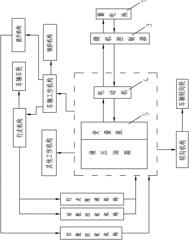
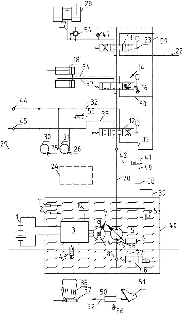
[0050] refer to figure 2 The hydraulic oil circuit diagram, specifically explaining the composition of each mechanism of the electronically controlled hydraulic drive system and how to realize the described functions.

[0051] The hydraulic oil tank is a multi-stage combined hydraulic oil tank, and the multi-stage combined hydraulic oil tank includes a lower oil tank 40, and an oil temperature sensor 2, a microcomputer controller 3, an electric motor 4, a variable displacement pump 5, and a speed sensor 7 are installed in the lower oil tank 40 , first check valve 8, hydraulic oil 10, liquid level sensor 11, kinetic energy regeneration solenoid valve 43, potential energy regeneration solenoid valve 46; motor 4 is coaxially connected with variable displacement pump 5; liquid level sensor 11 and oil temperature sensor 2 output The information is input to the microcomputer controller 3, and when the microcomputer controller 3 detects that the liquid level of the hydraulic oil 10 ...

Embodiment 2

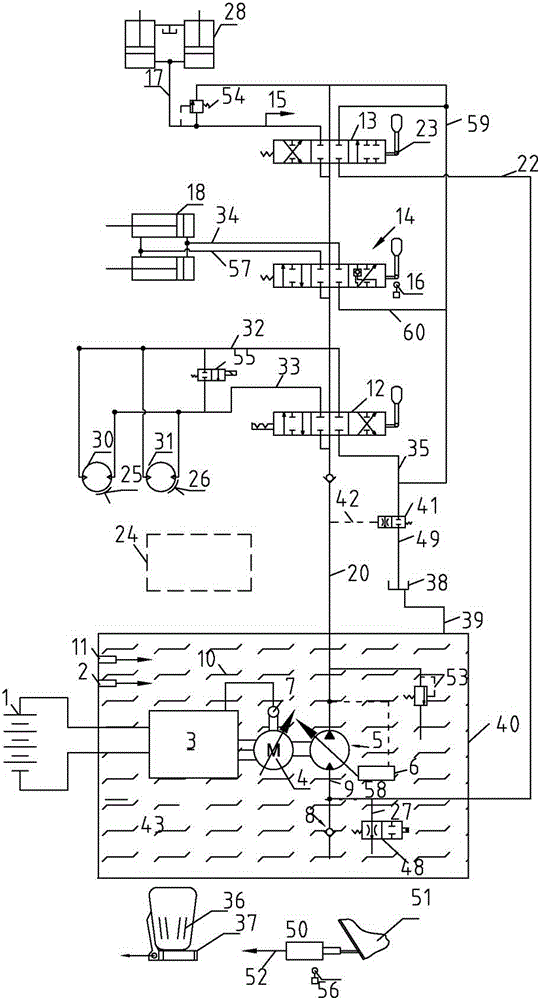
[0078] image 3 and figure 2 In comparison, the potential energy recovery mechanism is different, and other mechanisms are the same; specifically, the potential energy regeneration hydraulic valve 48 is used to replace the potential energy regeneration solenoid valve 46, and the oil circuit 15 is used to replace the pressure sensor 47 accordingly. For brevity, image 3 The kinetic energy recovery mechanism is omitted.

[0079] When the lift reversing valve 13 handle is switched to downshift, if the lift cylinder 28 is heavy-duty, the load hydraulic oil in the lift cylinder 28 pushes the potential energy regeneration hydraulic valve 48 through the oil circuit 15 to be in a closed circuit state, and the lift cylinder 28 The load hydraulic oil enters the oil inlet 58 of the variable pump 5 through the oil circuit 17, the lift reversing valve 13, and the oil circuit 22; due to the action of the first check valve 8, the variable variable pump 5 becomes a hydraulic motor at this ...

Embodiment 3

[0082] Figure 4 and image 3 Compared with that, a priority valve 19 is added, and other mechanisms are the same. For brevity, Figure 4 The kinetic energy recovery mechanism is omitted.

[0083] When the accelerator pedal 36 is stepped on, the accelerator sensor 37 sends an instruction to the microcomputer controller 3, and the motor 4 drives the variable pump 5 to output the hydraulic oil through the pipeline 20, and the hydraulic oil is delivered to the priority valve 19, and the output pipeline of the priority valve 19 is divided into two roads, One way is connected to the steering gear 24 (the effect of the priority valve 19 is to ensure the oil consumption of the steering gear 24), and the other way is connected to the travel reversing valve 12.


PUM


Abstract

The invention relates to an electric control hydraulic driving system for an industrial vehicle. Only one electromotor and one microcomputer controller are used for driving a variable pump to conduct frequency control so as to convey hydraulic oil in a hydraulic oil tank to a travelling mechanism, an inclining mechanism, a lifting mechanism, a steering mechanism, a kinetic energy recycling mechanism, a potential energy recycling mechanism and a travelling speed limiting mechanism; kinetic energy recycle, overload potential energy recycle, and no-load and light-load unloading can be realized while the vehicle realizes actions of travelling, inclining, lifting and steering; through the adoption of the travelling speed limiting mechanism, the vehicle speed can be limited, and the vehicle travelling can be stable; during slope sliding and braking, the hydraulic system can automatically supply oil; during slope climbing of the vehicle, the variable pump automatically varies according to the load pressure set value to achieve the low-speed large-torque slope climbing function, and the slope climbing current is low. The electromotor consists of a permanent-magnet brushless motor, an inverter controller and a variable piston pump; zero current start to a load current is realized, the starting time is within the millimeter-level range, large current starting can be avoided, and energy can be saved.

Description

technical field [0001] The invention belongs to the technical field of industrial vehicles, and in particular relates to an electronically controlled hydraulic drive system for industrial vehicles. Background technique [0002] Most of the off-highway mobile equipment and electric engineering vehicles sold and used in the market, including counterbalanced electric forklifts, reach electric forklifts, multi-directional electric forklifts and stacking electric vehicles, mostly use international advanced technology for their walking, lifting and tilting mechanisms. The popular three-phase AC asynchronous induction motor (referred to as AC motor), but these equipment and vehicles have the following defects: [0003] 1) The starting current is large; when the vehicle is frequently moving forward and backward, the current and energy consumption of the motor during braking and starting is large; [0004] 2) Large climbing current (requires 2 to 3 times the rated current); [0005...

Claims


Application Information

Patent Timeline
Patent Type & Authority Applications(China)
IPC IPC(8): B66F9/075B66F9/22F15B21/04F15B21/14B60K31/06
CPCB60L7/10B66F9/22F15B11/16F15B21/14
Inventor 彭昌宗萧子渊陈树国
Owner 上海市闸北区物流工程技术研究所
Why Eureka
Try Eureka