A kind of preparation method of metal-carbon nanotube composite porous electrode material

A carbon nanotube composite, porous electrode technology, applied in electrode manufacturing, hybrid/electric double layer capacitor manufacturing, battery electrodes, etc., can solve the problem of poor uniformity and consistency of carbon nanotubes, disordered surface orientation, and disordered pores order and other problems, to achieve uniform and orderly distribution of pipe diameter and length, improve performance and service life, and reduce the phenomenon of agglomeration and agglomeration.

Active Publication Date: 2019-09-06
WUZHOU HGP ADVANCED MATERIALS TECH CORP
View PDF10 Cites 0 Cited by
  • Summary
  • Abstract
  • Description
  • Claims
  • Application Information

AI Technical Summary

Problems solved by technology

[0005] In the prior art, there are mainly two types of related electrode materials that use carbon nanotubes and porous metal composites: the first is to mix carbon nanotubes with battery active materials and dry press or make a slurry and coat them on a porous metal substrate In general, the specific surface area of ​​the electrode prepared by this method has not been significantly improved, and the bonding force between the carbon nanotube and the matrix is ​​poor, and it is easy to peel under harsh application conditions.
The second is to grow carbon nanotubes on the porous metal surface. 3 Al alloy catalyzed method for preparing carbon nanotubes", and application publication number CN 104577059 "method for directly growing carbon nanotubes on foam nickel substrate to prepare battery electrodes") The technical scheme is to directly grow carbon nanotubes on the porous metal surface, This method is selective to the substrate, and only metals that can catalyze carbon nanotubes can be selected, and the obtained carbon nanotubes have poor uniformity in diameter and size, and the surface orientation is disordered, intertwined, and aggregated into clusters, making the gap between the channels The connection between them is disorderly and disorderly, which seriously affects the migration rate of electrolyte ions in the pores of the electrode material, thereby reducing the output power of the capacitor; method", and the application publication number is CN 102709569 "porous metal composite material") technical scheme is to form a layer of catalyst on the surface of the porous metal, and then grow carbon nanotubes on the catalyst. Long-term heat treatment will cause the catalyst particles to agglomerate, and at the same time form an alloy with the base metal, which will affect the catalytic performance of the catalyst, making the uniformity and consistency of the carbon nanotubes poor, and may lead to the deposition of amorphous carbon, affecting the performance of the electrode

Method used


Image

  • A kind of preparation method of metal-carbon nanotube composite porous electrode material

Examples


Embodiment 1

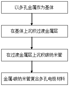
[0022] Using nickel foam as the substrate, the selected nickel foam has an average pore diameter of 100 μm and a thickness of 0.3 mm. Ni is deposited on the surface of the substrate as a transition metal layer using vacuum magnetron sputtering technology. The working parameters are: vacuum chamber background vacuum ≤ 5×10 -2 Pa, the pressure in the vacuum chamber during sputtering coating is ≤1Pa, the target power density applied per decimeter of target width is 0.1 kW to 1 kW, and the average thickness of the transition metal layer is 5 nm. In the vacuum furnace chamber, evacuate until the background vacuum inside the furnace chamber is ≤2 Pa, and then raise the temperature to 700 °C. During the heating process, argon gas is introduced as a protective gas. When the set temperature is reached, ethane gas is introduced. The volume ratio of gas to argon is 1:5, the reaction ends after 20 minutes, stop feeding ethane gas, and cool to room temperature under the protection of argon...

Embodiment 2

[0024] With aluminum foam as the substrate, the selected aluminum foam has an average pore diameter of 500 μm and a thickness of 1.5 mm. Co is deposited on the surface of the substrate as a transition metal layer using vacuum magnetron sputtering technology. The working parameters are: vacuum chamber background vacuum ≤ 5×10 -2 Pa, the pressure in the vacuum chamber during sputtering coating is ≤1Pa, the target power density applied per decimeter target width is 0.1 kW to 1 kW, and the average thickness of the transition metal layer is 350 nm. In the vacuum furnace cavity, vacuumize until the background vacuum inside the furnace cavity is ≤ 2 Pa, and then raise the temperature to 800 ° C. During the heating process, argon gas is introduced as a protective gas. When the set temperature is reached, methane gas is introduced. The methane gas and The volume ratio of argon is 1:2, and the reaction ends after 30 minutes. Stop feeding methane gas and cool to room temperature under th...

Embodiment 3

[0026] With nickel-iron foam as the substrate, the selected nickel-iron foam has an average pore diameter of 600 μm and a thickness of 2.5 mm. Ni-Co alloy is deposited on the surface of the substrate as a transition metal layer using vacuum magnetron sputtering technology. The working parameters are: vacuum Cavity background vacuum ≤5×10 -2 Pa, the pressure in the vacuum chamber during sputtering coating is ≤1Pa, the target power density applied per decimeter target width is 0.1 kW to 1 kW, the average thickness of the transition metal layer is 400 nm, and the Ni-Co alloy will be deposited on the surface Foam nickel-iron is placed in the vacuum furnace cavity, vacuumed until the background vacuum inside the furnace cavity is ≤2 Pa, and then heated up to 700 ℃, argon gas is introduced as a protective gas during the heating process, and ethylene gas is injected when the set temperature is reached , the volume ratio of ethylene gas to argon gas is 1:2, the reaction ends after 45 ...


PUM

PropertyMeasurementUnit
diameteraaaaaaaaaa
thicknessaaaaaaaaaa
diameteraaaaaaaaaa

Abstract

The invention discloses a preparation method of a metal-carbon nano tube compounded porous electrode material. The preparation method comprises the following steps: depositing a transition metal layer on a porous metal material, and then growing carbon nano tubes on the transition metal layer by taking the transition metal layer as a catalyst. The preparation method has the advantages that the carbon nano tubes growing on the porous substrate have less impurities, and are uniform, orderly, and high in consistency; the prepared electrode material is high in specific surface area and conductibility, and long in service life; the preparation process of the material is stable and efficient, so that convenience is brought for continuous production.

Description

technical field [0001] The invention relates to a preparation method of a porous electrode material, in particular to a preparation method of a metal-carbon nanotube composite porous electrode material. Background technique [0002] Electric energy is an indispensable secondary energy in human life and production in modern society. With the continuous development of social economy, its proportion is getting higher and higher. At present, in order to cope with the depletion of fossil energy and for the consideration of environmental protection, people are developing and utilizing renewable clean energy such as wind energy, water energy, and solar energy more and more widely. However, due to the limitation of natural conditions, the use of wind energy and Solar power generation is intermittent and not continuous. While reducing the construction scale of original power plants and increasing the proportion of renewable energy systems, in order to meet people's production and li...

Claims


Application Information

Patent Timeline
Patent Type & Authority Patents(China)
IPC IPC(8): H01G11/86H01M4/04H01M4/88
CPCY02E60/10Y02E60/50
Inventor 穆俊江韦雁途吴天和
Owner WUZHOU HGP ADVANCED MATERIALS TECH CORP
Why Eureka
Try Eureka