Porous electrode substrate, method for manufacturing same, and solid polymer fuel cell

A technology of a porous electrode and a manufacturing method, which is applied in the field of solid polymer fuel cells, can solve the problems of reduced power generation performance, hindered conductivity and gas diffusivity, and large interlayer structure changes, and achieves low manufacturing cost and sufficient conductivity. and the effect of gas diffusivity

Inactive Publication Date: 2016-01-06
MITSUBISHI CHEM CORP
View PDF11 Cites 4 Cited by
  • Summary
  • Abstract
  • Description
  • Claims
  • Application Information

AI Technical Summary

Problems solved by technology

In other words, from the perspective of the fuel cell as a whole, it is more important to reduce the contact resistance with adjacent parts than to reduce the intrinsic resistance of the porous electrode substrate. So far, no porous electrode substrate has been proposed from this point of view.
[0009] In addition, since the interlayer structure between MPL and the porous electrode substrate changes greatly, the interface between the two layers hinders electrical conductivity and gas diffusion, and also hinders the drainage of generated water during power generation, and power generation performance may be greatly reduced.

Method used


Image

  • Porous electrode substrate, method for manufacturing same, and solid polymer fuel cell
  • Porous electrode substrate, method for manufacturing same, and solid polymer fuel cell
  • Porous electrode substrate, method for manufacturing same, and solid polymer fuel cell

Examples


Embodiment 1

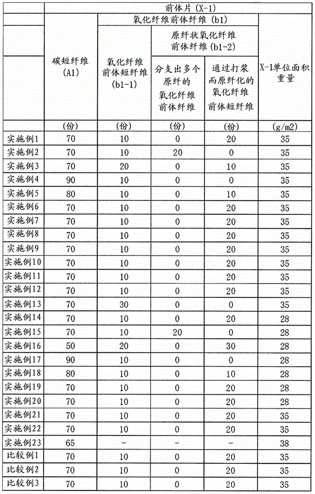
[0238] As short carbon fibers (A), PAN-based carbon fibers having an average fiber diameter of 7 μm and an average fiber length of 3 mm were prepared. Also, short acrylic fibers (manufactured by Mitsubishi Rayon Corporation, trade name: D122) with an average fiber diameter of 4 μm and an average fiber length of 3 mm were prepared as the oxidized fiber precursor short fibers (b). In addition, as oxidized fiber precursor short fibers fibrillated by beating, a splittable acrylic sea-island composite composed of acrylic polymer and diacetate (cellulose acetate) fibrillated by beating was prepared. Short fibers (manufactured by Mitsubishi Rayon Corporation, trade name: Vonnel M.V.P.-C651, average fiber length: 3 mm).

[0239] The production of the precursor sheet and the precursor sheet of the three-dimensional entangled structure obtained by the entanglement process were carried out by the following wet continuous papermaking method and the entanglement process by continuous press...

Embodiment 2~5

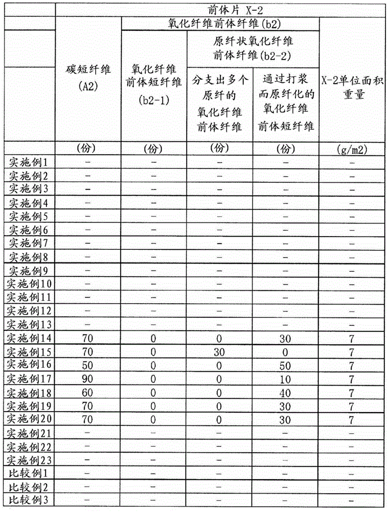
[0272] Using the dissociated pulp fibers (SA), dissociated pulp fibers (Sb-1) and dissociated pulp fibers (Sb-2) shown in Example 1, short carbon fibers (A) and oxidized fiber precursors A porous electrode substrate was obtained in the same manner as in Example 1 except that the mass ratio of short fibers and fibrillar oxidized fiber precursor fibers was set to the conditions shown in Tables 1 to 3. The obtained porous electrode substrate had no in-plane shrinkage during heat treatment, the sheet waviness was as small as 2 mm or less, and the gas permeability, thickness, and through-direction resistance were all good. Moreover, the content rate of each oxidized fiber (B) is shown in Tables 1-2. It can be confirmed that the short carbon fibers (A) dispersed in the three-dimensional structure of the obtained porous electrode substrate are bonded to each other by the oxidized fibers (B), and the short carbon fibers (A) and the oxidized fibers (B) are bonded by the carbon powder (...

Embodiment 6~11

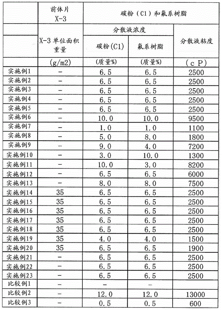
[0274] A porous electrode substrate was obtained in the same manner as in Example 1 except that preparation of a dispersion liquid of a mixture of carbon powder (C) and a fluorine-based resin was carried out under the conditions shown in Tables 1 to 3. Table 3 shows the viscosity of each dispersion liquid. The obtained porous electrode substrate had no in-plane shrinkage during heat treatment, the sheet waviness was as small as 2 mm or less, and the gas permeability, thickness, and through-direction resistance were all good. Moreover, the content rate of the oxidized fiber (B) was 29 mass % with respect to the whole mass of the porous electrode base material. It can be confirmed that the short carbon fibers (A) dispersed in the three-dimensional structure of the obtained porous electrode substrate are bonded to each other by the oxidized fibers (B), and the short carbon fibers (A) and the oxidized fibers (B) are bonded by the carbon powder (C) Bonded with fluororesin. Furthe...


PUM

PropertyMeasurementUnit
thicknessaaaaaaaaaa
densityaaaaaaaaaa
thicknessaaaaaaaaaa

Abstract

One purpose of this invention is to provide a porous electrode substrate that has a low manufacturing cost, has sufficient conductivity and gas diffusion characteristics, and shows favorable power generation ability with minor structural changes in the porous electrode substrate, as well as a method for manufacturing such a porous electrode substrate. An additional purpose of this invention is to provide a membrane-electrode joint and a solid polymer fuel cell that comprise such a porous electrode substrate. This invention is: a method for manufacturing a porous electrode substrate that comprises a step (1) in which a dispersion fluid comprising a carbon powder (C) and a fluorine-based resin is applied to one or both surfaces of a precursor sheet wherein carbon short fibers (A1) are dispersed in planar orientations with the fiber orientations being substantially within the same plane, and as a result the fluorine-based resin that contains the carbon powder (C) in the vicinity of the surface layer of one side or both sides of the precursor sheet is distributed unevenly to form a precursor sheet with unevenly-distributed fluorine-based resin, and a step (2) in which after the aforementioned step (1) the precursor sheet with unevenly-distributed fluorine-based resin is heat-treated at a temperature 150 DEG C or higher and less than 400 DEG C; a porous electrode substrate manufactured using this manufacturing method; and a solid polymer fuel cell that uses this porous electrode substrate.

Description

technical field [0001] The present invention relates to a porous electrode substrate that can be used in a fuel cell, a method for producing the same, a membrane-electrode assembly including the porous electrode substrate, and a solid polymer fuel cell. [0002] This application claims priority based on Japanese Patent Application No. 2013-100109 for which it applied in Japan on May 10, 2013, and Japanese Patent Application No. 2013-233850 for which it applied in Japan on November 12, 2013, and uses the content here. Background technique [0003] In the past, in order to improve the mechanical strength, the gas diffusion electrode substrate installed in the fuel cell is a porous electrode substrate composed of a paper-like carbon / carbon composite. A thermosetting resin is used to bond it, and it is fired at a high temperature to carbonize an organic polymer (refer to Patent Document 1). [0004] In addition, for the purpose of cost reduction, a porous electrode substrate in...

Claims


Application Information

Patent Timeline
Patent Type & Authority Applications(China)
IPC IPC(8): H01M4/88H01M4/86H01M4/96H01M8/10
CPCB32B5/022B32B5/06B32B5/22B32B5/26B32B2250/20B32B2255/02B32B2255/26B32B2260/023B32B2262/02B32B2262/0223B32B2262/023B32B2262/0246B32B2262/106B32B2264/108B32B2307/202B32B2307/50B32B2307/724B32B2307/734B32B2457/00B32B2457/18H01M4/8605H01M4/8807H01M4/8817H01M8/0234H01M8/0239H01M8/0243H01M8/0245H01M2008/1095Y02E60/50Y02P70/50D04H1/42H01M4/8642
Inventor 隅冈和宏
Owner MITSUBISHI CHEM CORP
Why Eureka
Try Eureka