Manufacturing method for carbon-graphite floating ring

A carbon graphite, floating ring technology, applied in mechanical equipment, engine seals, engine components, etc., can solve the problems of increasing product leakage, large thermal expansion coefficient, shedding, etc., to achieve good comprehensive thermal expansion coefficient, good electrical conductivity, good air tightness

Inactive Publication Date:
View PDF7 Cites 7 Cited by
  • Summary
  • Abstract
  • Description
  • Claims
  • Application Information

AI Technical Summary

Problems solved by technology

Disadvantages of floating ring seals: the manufacturing precision of the seals is high, and the non-concentricity of the rings, the non-perpendicularity of the end faces and the surface roughness have a significant impact on the sealing performance
The disadvantage of the traditional process is that the carbon graphite floating ring and the metal inlaid ring 1 are bonded together by high-temperature glue, and there are many gaps between the bonding surfaces. Under high pressure, the bonding will leak
And because the thermal expansion coefficient of carbon and graphite materials is small, and the thermal expansion coefficient of the metal ring 1 material is relatively large, the traditional technology uses high-temperature glue to put the gap fit into the carbon, graphite ring and metal ring 1 to stick together, and there is a gap between them. There is a gap. When the temperature is high, due to the inconsistent thermal expansion coefficients of the two, a new gap is likely to be formed. In addition to its original gap, the leakage of the product will be increased, and even carbon, graphite rings and The metal rings are loose and fall off, thus making the seal invalid

Method used


Image

  • Manufacturing method for carbon-graphite floating ring
  • Manufacturing method for carbon-graphite floating ring

Examples


Embodiment Construction

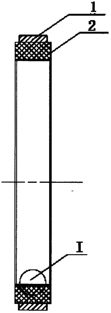
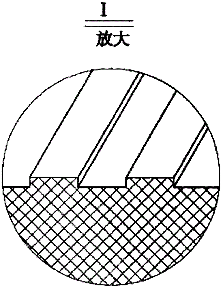
[0012] refer to figure 1 , figure 2 . The carbon-graphite floating ring 2 is composed of two parts. The carbon-graphite floating ring is wrapped with a metal ring 1 outside, the carbon-graphite sealing ring is inside, and the stainless metal ring 1 is outside. In order to form a gas film as soon as possible in the process of operation, and better play a sealing effect, the carbon graphite floating ring 2 can be formed with an annular small groove or a multi-thread. First process the carbon graphite floating ring and metal inlaid ring 1 with processing allowance, and use interference fit between the carbon graphite floating ring and metal inlaid ring 1. The size of the interference can be based on the size of the carbon graphite floating ring 2 product Adjust with the use temperature, such as the larger the size of the carbon graphite floating ring 2, the greater the interference, the higher the final use temperature, the higher the heating temperature of the metal insert ri...


PUM


Abstract

The invention discloses a manufacturing method for a carbon-graphite floating ring. According to the manufacturing method, combination surfaces of a graphite ring and a peripheral metal inlaid ring are combined reliably, thermal conductivity and electrical conductivity are good, and no blister scar is generated. According to the technical scheme for implementing the manufacturing method, the carbon-graphite ring and the metal inlaid ring which have working allowances are processed firstly, and the carbon-graphite ring is in interference fit with the metal inlaid ring; then the metal inlaid ring is heated to 280-320 DEG C in a heating furnace, the carbon-graphite ring is rapidly arranged in the metal inlaid ring in the interference fit mode, and the carbon-graphite ring and the metal inlaid ring are cooled naturally; afterwards, a floating ring assembly formed after inlaying is placed in a vacuum reaction kettle, thermosetting resin is added, micro gaps between the carbon-graphite ring and the metal ring are fully filled with the thermosetting resin, and the thermosetting resin is sintered at a high temperature to be completely carbonized; and finally finish machining is carried out, and the finished floating ring is obtained. Through the manufacturing method, the problems that according to a traditional process, the carbon-graphite ring and the metal inlaid ring are combined through high-temperature adhesive, a great number of gaps are formed between combination surfaces, and leakage occurs to the combination position under high pressure are solved.

Description

technical field [0001] The invention relates to a preparation method of a carbon graphite floating ring floating ring. Background technique [0002] With the improvement of equipment working parameters, a large number of hard sealing rings made of carbon graphite anti-wear materials have been used to ensure that the equipment can work reliably in no lubricant and high-speed high-temperature or corrosive media. In steam turbines, gas turbines, pistons Type or turbine compressors, steam engines, pumps, gas compressors, submersible pumps, clean water pumps, nuclear diode pumps, boiler feed pumps, dryers, textile printing and dyeing machines, water pumps, heat setting machines, shielded pumps, separators, dust collectors Device, steam flow meter, high temperature heat oil pump, aircraft engine, fuel tank, starter motor, cigarette machine, fan, clutch device, steam turbine, soda ash calciner furnace, centrifugal pump, compressor, vacuum pump, fermenter water turbine, vacuum heate...

Claims


Application Information

Patent Timeline
Patent Type & Authority Applications(China)
IPC IPC(8): F16J15/30
Inventor 侯玉杰程诺
Why Eureka
Try Eureka