Device and method for waste heat recovery of high-temperature molten slag by means of two-step method

A waste heat recovery device and high-temperature melting technology, applied in furnaces, waste heat treatment, furnace components, etc., can solve the problems of insufficient recovery and utilization of thermal energy of high-temperature molten slag, deteriorating labor conditions on production sites, and no recovery of high-temperature thermal energy, etc., to save layout space, improving working conditions, and saving energy

Active Publication Date: 2016-01-27
NANJING SHENGNUO HEAT PIPE
View PDF7 Cites 10 Cited by
  • Summary
  • Abstract
  • Description
  • Claims
  • Application Information

AI Technical Summary

Problems solved by technology

However, the water quenching process has the following hidden dangers and disadvantages: (1) the water quenching method needs to consume a large amount of water to reduce its high temperature; (2) some harmful elements in the high temperature molten slag will pollute water resources and air; (3) high temperature The molten slag contains a large amount of high-temperature heat energy that is not recovered and is wasted; (4) The working conditions on the production site deteriorate and there are potential safety hazards
Although this invention adopts the heat recovery of high-temperature molten slag step by step, the treatment of high-temperature molten slag is to recover part of the waste heat in the jacket tube, and then directly send it into the water slag tank for water quenching treatment, which requires a lot of water consumption. If the high temperature is lowered, the phase of the obtained slag particles is not good, the content of the glass phase is not high, and the high-temperature molten slag contains a large amount of heat energy, which is not fully recovered; since the high-temperature molten slag is directly subjected to water quenching, in order to enhance the heat transfer effect, it is necessary to use a jacket Cooling water or steam is passed into the tube for heat exchange, which increases the complexity of the equipment

Method used


Image

  • Device and method for waste heat recovery of high-temperature molten slag by means of two-step method
  • Device and method for waste heat recovery of high-temperature molten slag by means of two-step method

Examples


Embodiment Construction

[0030] The present invention will be further described below in conjunction with accompanying drawing:

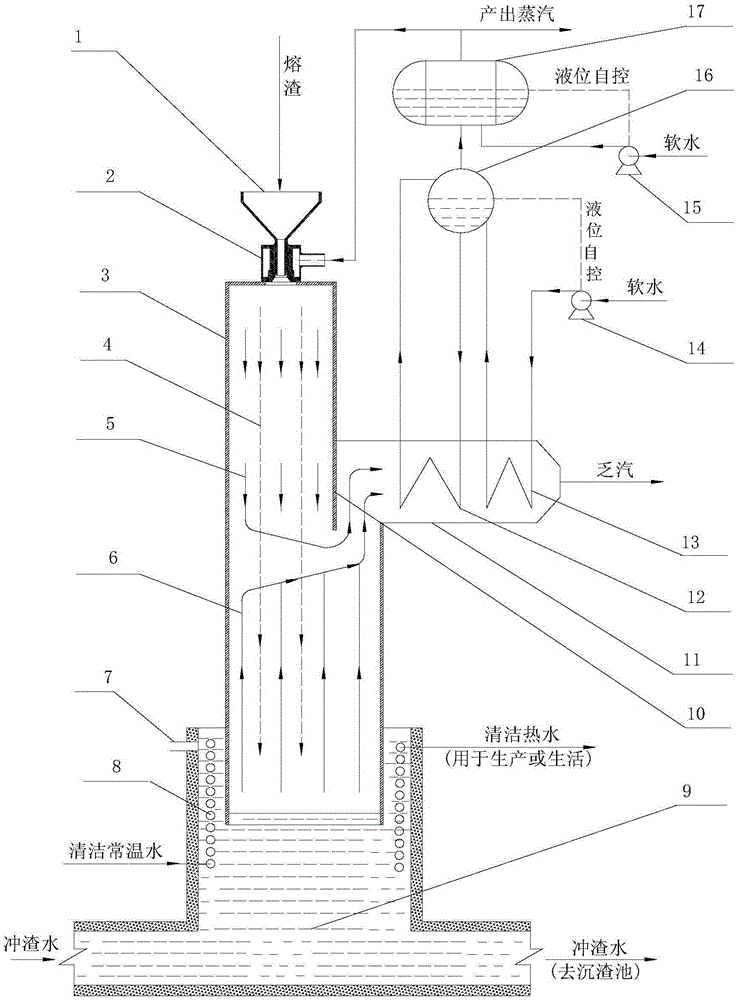
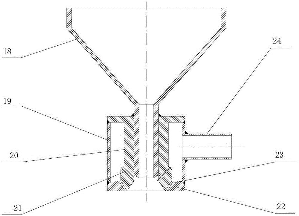
[0031] like figure 1 As shown, the high-temperature molten slag waste heat recovery device provided by the present invention includes a jet granulator 2, a granulation cylinder 3, a water slag pool 9, a spiral tube heat exchanger 8, a heat exchanger flue 11, and a steam drum 16 , Regenerator 17 and so on. The granulation cylinder 3 can be a circular cylinder or a square cylinder. The lower end of the granulation cylinder 3 is inserted into the water slag pool 9. The insertion requirement is that there is a pressure difference between the inside and outside of the lower end of the granulation cylinder. To form a liquid level difference, the height from the water level in the slag pool 9 to the lower end surface of the granulation cylinder 3 is greater than the height of the water level drop in the granulation cylinder 3 due to positive pressure, ensuring that the lower end ...


PUM

PropertyMeasurementUnit
specific heat capacityaaaaaaaaaa

Abstract

The invention provides a device for waste heat recovery of high-temperature molten slag by means of a two-step method. The device comprises a jet pelletizer, a pelletizing barrel and a granulating pit. The lower end of the pelletizing barrel is inserted in the granulating pit, and a liquid level difference is formed due to the difference of inner pressure and outer pressure of the lower end of the pelletizing barrel. The upper end of the pelletizing barrel is connected with a discharging opening of the jet pelletizer. The pelletizing barrel is communicated with a heat exchanger flue, an evaporator is arranged in the heat exchanger flue and connected with a steam bag through a condensation liquid descending pipe and a steam ascending pipe. Waste heat recovery is achieved by means of the two-step method, saturated steam jet pelletizing are firstly carried out on the high-temperature molten slag to form slag particles, superheated steam is generated, and high-grade waste heat is recovered; and water quenching is carried out before the slag particles are solidified, water granulated slag with the high glass phase content is obtained, and low-grade waste heat is recovered. The process is simple, the molten slag waste heat recovery rate is high, energy consumption is reduced, a few of devices are needed, and the size is small. The device can be widely applied to waste heat recovery of blast furnace slag, phosphorus slag and other high-temperature molten slag.

Description

technical field [0001] The invention relates to a waste heat recovery system in the fields of phosphorus chemical industry, metallurgy, energy conservation and environmental protection, and in particular to a waste heat recovery device and a waste heat recovery method of a high-temperature molten slag two-step method. Background technique [0002] Phosphorus chemical industry, metallurgy, energy conservation and environmental protection and other fields all produce high-temperature molten slag as a by-product in the production process. These high-temperature molten slags have the characteristics of high temperature and high enthalpy, and belong to high-quality waste heat resources. For example, blast furnace slag is a by-product of blast furnace ironmaking. The temperature discharged from the blast furnace is 1450-1650 °C, and the enthalpy is about 1870MJ / t; the molten phosphorus slag discharged from the yellow phosphorus electric furnace is about 1400 °C, and the enthalpy i...

Claims


Application Information

Patent Timeline
Patent Type & Authority Applications(China)
IPC IPC(8): F27D17/00
CPCY02P10/25Y02P80/15
Inventor 陈兴元杨峻郭宏新陈军詹岳汪夏
Owner NANJING SHENGNUO HEAT PIPE
Why Eureka
Try Eureka