Piston ring, raw material therefor, and production method for both
A manufacturing method and technology of piston rings, applied in the field of piston rings, can solve problems such as difficult manufacturing methods and material properties, difficulty in reducing weight and narrowing width, reliability is not practical, etc., achieve excellent thermal fatigue resistance, reduce removal amount , Excellent sealing effect
- Summary
- Abstract
- Description
- Claims
- Application Information
AI Technical Summary
Problems solved by technology
Method used
Image

Examples
Embodiment 1
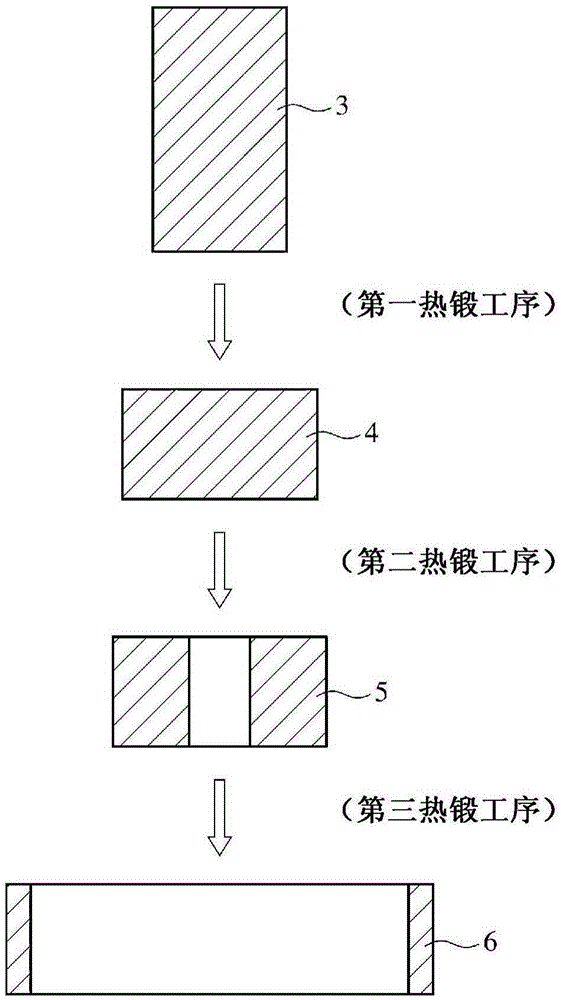
[0064] Heat a bar steel of SUS420J2 material with an outer diameter of 110mm and a length of 200mm to 1000°C, press and form it into a disc shaped body with an outer diameter of 165mm and a height of about 90mm, and then form a concave part in the center with a core punch, and penetrate it , Open a hole, and make the first cylindrical raw material with an outer diameter of about 180mm and an inner diameter of about 50mm. Next, the first cylindrical raw material is reheated by a high-frequency induction heating device, installed in a hole-enlarging machine, and rolled to produce a second cylindrical material with an outer diameter of about 364 mm, an inner diameter of about 332 mm, and a width of about 110 mm. Two cylindrical raw materials. After the second cylindrical raw material was annealed at 790°C for 10 hours, after the scale was removed by sandblasting, the inner and outer peripheries were simultaneously rough-machined into a non-circular shape (elliptical shape) with a...
Embodiment 2
[0072] Using steel materials with the same composition as in Example 1, a second cylindrical raw material having an outer diameter of about 368 mm, an inner diameter of about 339 mm, and a width of about 120 mm was produced by rolling and reaming, and the cylindrical raw material was heated again. Press forming is carried out in a direction perpendicular to the axis, and formed into a non-circular cylindrical material with a major axis of 370 mm and a minor axis of 364 mm. In this press forming, a lower mold and an upper mold having a predetermined elliptical shape are used. The obtained noncircular cylindrical raw material was subjected to annealing and descaling by sandblasting in the same manner as in Example 1, followed by simultaneous processing of inner and outer peripheries and piercing processing to obtain 8 noncircular rings. In the same manner as in Example 1, after quenching and tempering, finishing was performed, and then nitriding and thermal spraying were perform...
Embodiment 3~7
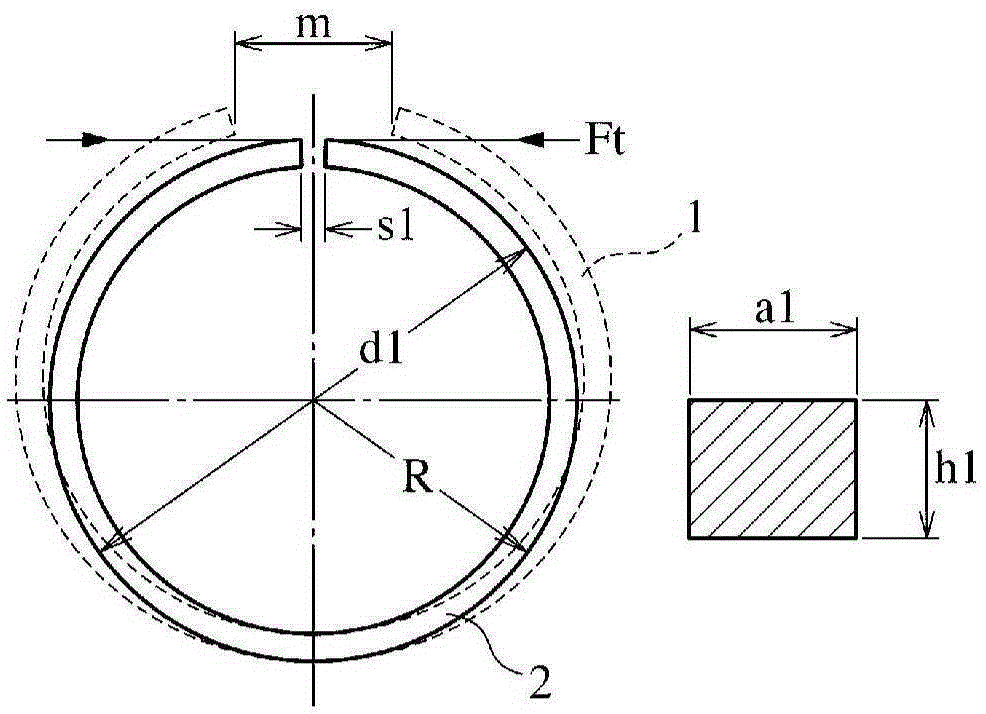
[0074] From the second cylindrical material with an outer diameter of about 368 mm, an inner diameter of about 339 mm, and a width of about 120 mm produced in Example 2, except that the nominal diameter (d1) was set to 350 mm, the ring width (h1) and radial thickness ( a1) The numerical values shown in Table 1 were used, and eight pressure rings were produced for each example in the same manner as in Example 2, except that the tension Ft was adjusted so that the surface pressure would be 0.08 MPa. Table 1 shows the dimensional relationship and the tension Ft relationship, and Table 2 shows the measurement results of the weight and flatness measured in the same manner as in Example 1, and the weight ratio and followability coefficient ratio relative to Comparative Example 1, and also The results of Example 1 and Comparative Example 1 are included. Here, the Young's modulus (E) of the steel material of Example 1 is set to 215 GPa, and the Young's modulus (E) of the cast iron o...
PUM
| Property | Measurement | Unit |
|---|---|---|
| diameter | aaaaa | aaaaa |
| diameter | aaaaa | aaaaa |
| Vickers hardness | aaaaa | aaaaa |
Abstract
Description
Claims
Application Information
 - R&D
- Intellectual Property
- Life Sciences
- Materials
- Tech Scout
- Unparalleled Data Quality
- Higher Quality Content
- 60% Fewer Hallucinations
Browse by: Latest US Patents, China's latest patents, Technical Efficacy Thesaurus, Application Domain, Technology Topic, Popular Technical Reports.
© 2025 PatSnap. All rights reserved.Legal|Privacy policy|Modern Slavery Act Transparency Statement|Sitemap|About US| Contact US: help@patsnap.com