Energy conservation and emission reduction modification method for reducing emission load of nitric oxide of DDF decomposing furnace

A technology for energy conservation, emission reduction, and nitrogen oxides, which is applied in combustion methods, furnaces, and furnace components, etc., can solve the problems of increasing the heat loss of chemical incomplete combustion, insufficient pulverized coal combustion, and insufficient residence time, and achieves an increase in the average residence time. effect of time, reduction of excess air coefficient, and simple method

Active Publication Date: 2016-02-03
BEIJING TRIUMPH INT ENG
View PDF6 Cites 4 Cited by
  • Summary
  • Abstract
  • Description
  • Claims
  • Application Information

AI Technical Summary

Problems solved by technology

At present, many cement kiln calciners are designed for historical reasons. The early design improperly emphasized the unit volume output of the calciner. The volume of the calciner is too small, and the residence time of pulverized coal in the furnace is insufficient, which directly affects the decomposition Insufficient combustion of pulverized coal in the furnace may easily lead to a considerable proportion of reducing gas with a large amount of potential and CO as the main symbol in the kiln flue gas discharged from the first-stage cyclone preheater, which unnecessarily increases chemical incomplete combustion heat loss

Method used


Image

  • Energy conservation and emission reduction modification method for reducing emission load of nitric oxide of DDF decomposing furnace
  • Energy conservation and emission reduction modification method for reducing emission load of nitric oxide of DDF decomposing furnace

Examples


Embodiment

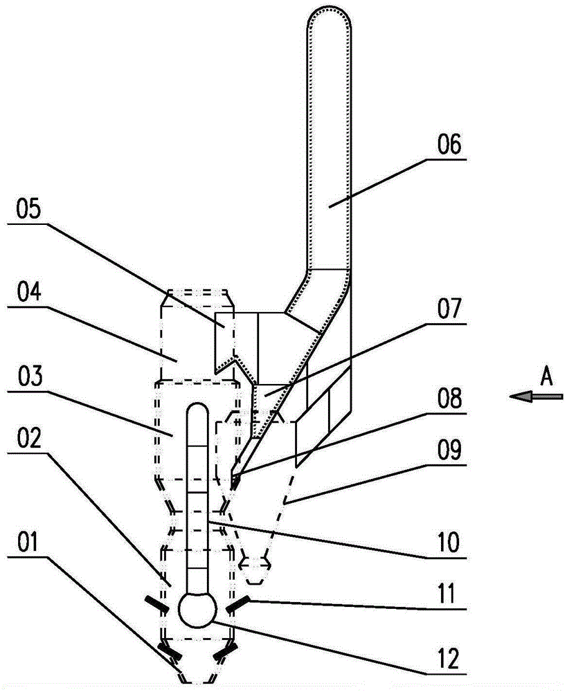
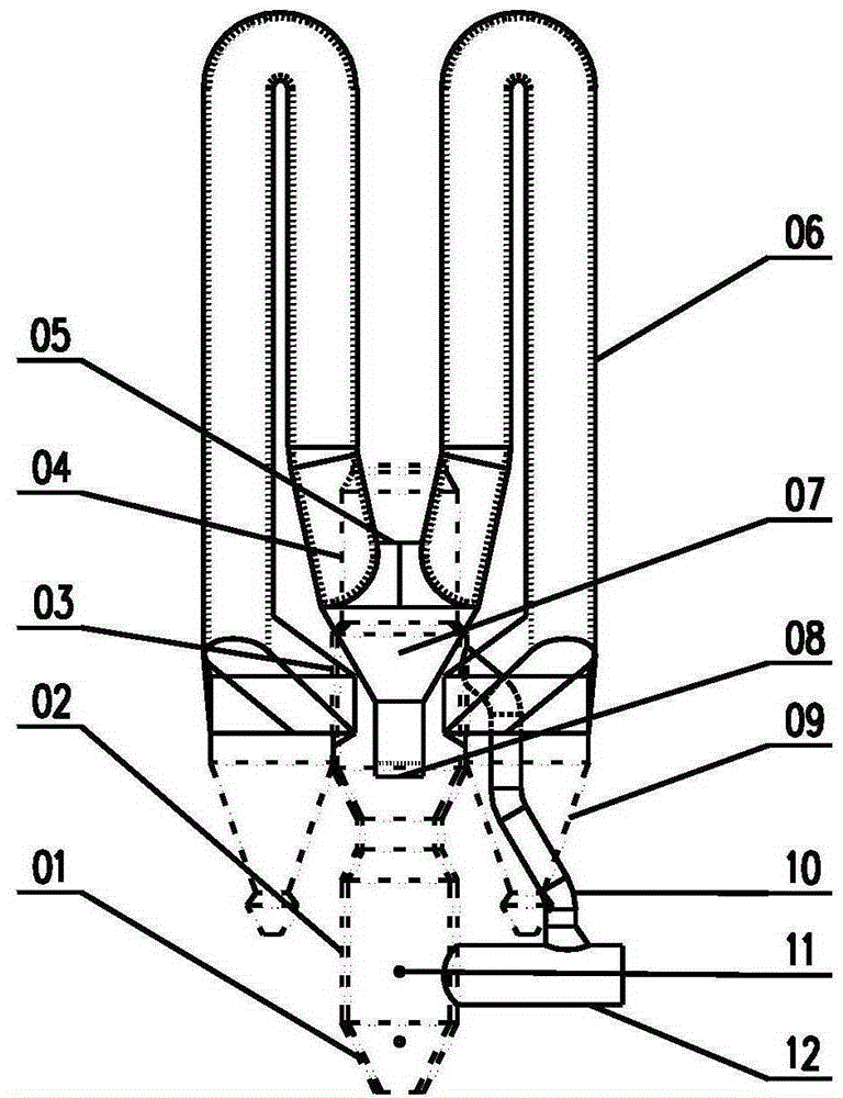
[0021] The volume of the existing calciner in a cement plant is only 300m 3 , when the output is 2100t / d, the residence time of the hot air in the calciner is only 2.0s, the connecting pipe from the calciner to the fifth-stage preheater is very short, and the daily output per unit capacity of the calciner is as high as 7.5t / m 3 d. It is recommended that the daily output per unit furnace capacity should not be higher than 4t / m 3d. The furnace capacity is obviously too small, which directly affects the insufficient combustion of pulverized coal in the calciner. After the transformation, it is planned to expand the calciner furnace by extending the combustion space to the outside of the frame, adding a horizontal confluence flue gas pipe and two symmetrically arranged external gooseneck pipes with a diameter of 2900mm when the calculation is performed at 2300t / d capacity, increasing the furnace capacity by 2.4 times to 720m 3 , the residence time of hot air is extended to 4.8s,...


PUM


Abstract

The invention discloses an energy conservation and emission reduction modification method for reducing the emission load of nitric oxide of a DDF cement decomposing furnace. By arranging an air gathering bellows and a gooseneck pipe on the DDF decomposing furnace with the small volume, the smoke standing time is prolonged; part of coal powder is distributed to the conical portion of the decomposing furnace, part of tertiary air is distributed to the upper middle portion of the decomposing furnace, the volume of the DDF decomposing furnace is enlarged, the position of part of coal powder entering the furnace is reduced, and the coal powder burn-off rate is improved. The coefficient of excess air in the lower middle portion of the decomposing furnace is smaller than 1.0. Under the condition of insufficient oxygen, CO of a large proportion is generated to become reducing agents for reducing and eliminating nitric oxide. An ash returning channel is arranged inside the air gathering bellows and feeds raw materials and coal powder particles subsided back to the position above a middle nozzle of the decomposing furnace, so that the problem of sintering blockage of accumulated ash is solved, the coarse particle processing capacity of the decomposing furnace is improved, the decomposition rate of raw materials entering the furnace is improved, and through the double effects of reducing emission of nitric oxide and reducing heat loss, the effective energy conservation and emission reduction of a cement calcining system are achieved.

Description

technical field [0001] The invention relates to the field of energy saving and emission reduction of cement kilns, in particular to a method for transforming a DDF cement decomposition furnace for energy saving and emission reduction. Background technique [0002] During the high-temperature calcination process of cement kiln, various forms of nitrogen oxides will be generated. Through targeted transformation of the decomposition furnace of cement kiln, the emission of nitrogen oxides can be effectively suppressed. The calciner mainly reduces the emission of nitrogen oxides through staged combustion of fuel or staged air supply. The staged combustion of fuel is mainly to divide the fuel into two parts (or more parts) and spray them into different positions of the calciner. Part of the fuel is sent to the cone part with low oxygen content through the auxiliary pulverized coal burner at the lower part of the calciner. area, under the conditions of higher flue gas temperature ...

Claims


Application Information

Patent Timeline
Patent Type & Authority Applications(China)
IPC IPC(8): F23C5/08F23C7/00F27D13/00F27D17/00
Inventor 马明亮谢吉优姜敬宝王业华陆秉权杨红彩项泽强马海涛
Owner BEIJING TRIUMPH INT ENG
Why Eureka
Try Eureka