
Method for manufacturing hybrid transparent electrode and hybrid transparent electrode

A technology of transparent electrodes and manufacturing methods, applied in cable/conductor manufacturing, replication/marking methods, conductive materials dispersed in non-conductive inorganic materials, etc. Energy barrier and other problems, to achieve the effect of excellent interface characteristics, high conductivity, and excellent conductivity

Inactive Publication Date: 2016-03-09
INKTEC CO LTD
View PDF6 Cites 6 Cited by
  • Summary
  • Abstract
  • Description
  • Claims
  • Application Information

AI Technical Summary

Problems solved by technology

[0004] However, the electrode surface formed of these materials is not suitable for other display processes such as OLEDs that require surface flatness of tens of nanometers, and may be Will increase the energy barrier
[0005] Currently, indium tin oxide (IndiumTinOxide, ITO)-based oxide transparent electrodes are commercially used on transparent electrodes for touch panels and displays, but the reserves are limited, and they lack flexibility in oxide characteristics and have no resistance characteristics. Metal is excellent, so it is not suitable for use as a large-area flexible display

Method used


Image

  • Method for manufacturing hybrid transparent electrode and hybrid transparent electrode
  • Method for manufacturing hybrid transparent electrode and hybrid transparent electrode
  • Method for manufacturing hybrid transparent electrode and hybrid transparent electrode

Examples


preparation example Construction

[0085] Conventional methods for preparing metal nanoparticles include a physical method of pulverizing metal lumps and a chemical method. Further details of the chemical method include: aerosol method of spraying high-pressure gas to make powder, pyrolysis method of using metal compound and gas reducing agent to make powder by pyrolysis, heating and evaporating raw materials Evaporation concentration method, sol-gel method, hydrothermal synthesis method, ultrasonic synthesis method, microemulsion method and liquid phase reduction method to make powder.

[0086] The most commonly used is the liquid phase reduction method, which utilizes a dispersant and a reducing agent to prepare, which is easy to control the formation of nanoparticles, and is evaluated as the method with the best economic effect, but in the present invention, as long as nanoparticles can be formed, All methods can be used.

[0087] For a specific description of the method for preparing nanoparticles by the l...

preparation example 1

[0158] Mix 27.98 g of conductive paste (prepared by Yin Ke De Co., Ltd.) and 0.45 g of terpineol (terpineol) in 1.57 g of ink (produced by Yin Ke De Co., Ltd.) for coating, and utilize a slurry mixer (Dahua Technology Co., Ltd.) ) was stirred at 1000 rpm for six minutes to prepare a conductive ink composition.

preparation example 2

[0160] After adding 10.0 g of isobutyl carbamate, 85.5 g of isobutylamine, and 2.0 g of a 95% solution of 2-amino-2-methyl-1 propanol, 2.5 g of hydrogen peroxide was added slowly, followed by stirring for five minutes to prepare etchant.


PUM

PropertyMeasurementUnit
Thicknessaaaaaaaaaa
Thicknessaaaaaaaaaa
Surface roughnessaaaaaaaaaa

Abstract

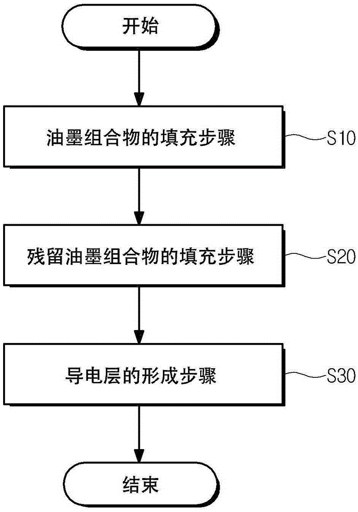
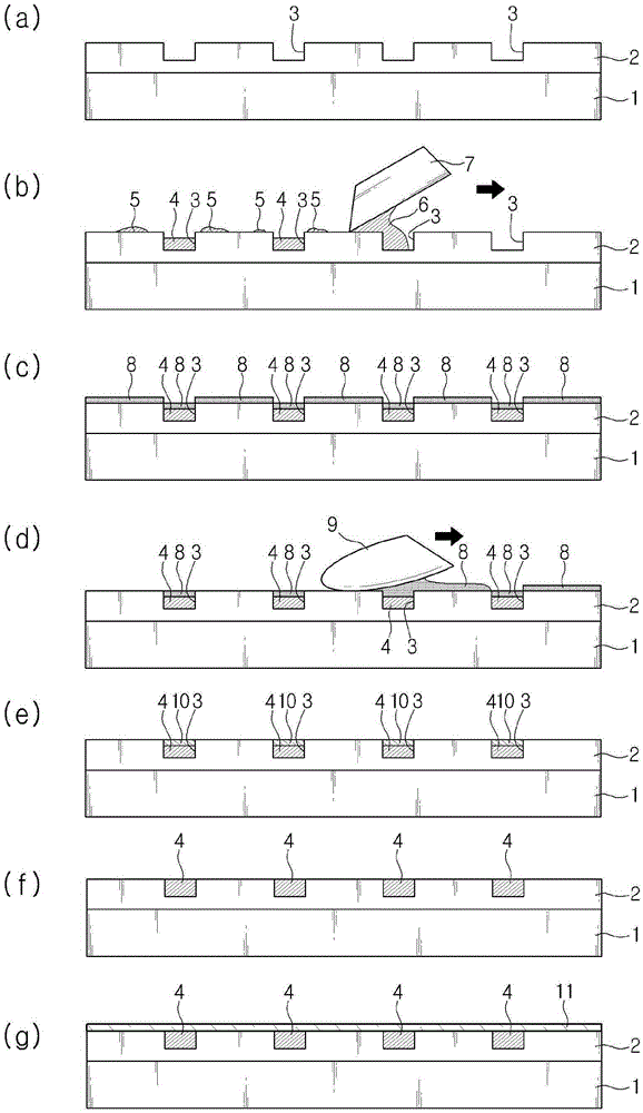
The present invention relates to a method for manufacturing a hybrid transparent electrode and a hybrid transparent electrode, the method comprising: an ink composition filling step for filling a conductive metal ink composition into a groove on a base material having the groove; a remaining ink composition filling step of forming an electrode pattern by filling the groove with the conductive metal ink composition remaining on the surface of the base material, as the conductive metal ink composition is filled in the groove; and a conductive layer forming step of forming a conductive layer comprising a conductive material on top of the electrode pattern.

Description

technical field [0001] The present invention relates to a method for manufacturing a hybrid transparent electrode and the hybrid transparent electrode, and more specifically, to a method for manufacturing a hybrid transparent electrode in which a conductive layer is formed on a metal fine electrode pattern. Background technique [0002] Recently, with the trend of thinner and smaller electronic products, electronic components such as displays and transistors are required to be produced in a high-density and high-integration form. Therefore, the technology for forming metal patterns that can be used on electrodes or wiring (metallization) much attention. [0003] Especially in the production technology of transparent electrodes necessary for touch panels, forming a fine pattern on a base and filling the metal pattern with conductive metal ink is very useful in terms of resistance characteristics. In addition, a metal-based transparent electrode (TCF) that coats metal nanowir...

Claims


Application Information

Patent Timeline
IPC IPC(8): H01B13/00H01B5/14
CPCG06F3/041G06F2203/04103G06F2203/04112B41M5/00C09D11/52H01B1/20H01B1/22H01B5/14H01B13/00H01B13/322G06F3/044
Inventor 郑光春李仁淑柳志勳成俊基韩大尚
Owner INKTEC CO LTD
Learn More