
A low-loss radiation-resistant birefringent photonic crystal fiber

A technology of photonic crystal fiber and birefringence, which is applied in the direction of multi-layer core/cladding fiber, cladding fiber, optical waveguide light guide, etc., can solve the problems that photonic crystal fiber cannot meet and limit, and achieve good anti-radiation performance , good low loss, and guaranteed radiation resistance

Active Publication Date: 2018-01-02
FENGHUO COMM SCI & TECH CO LTD +1
View PDF5 Cites 0 Cited by
  • Summary
  • Abstract
  • Description
  • Claims
  • Application Information

AI Technical Summary

Problems solved by technology

[0005] However, the existing photonic crystal fiber is still limited to a simple replacement of the performance of the conventional polarization-maintaining fiber, that is, a good birefringence effect can be achieved through the arrangement of air holes to replace the birefringence effect of the conventional polarization-maintaining fiber
For the reduction of fiber loss and the improvement of radiation resistance performance, there are still certain restrictions, so that the existing photonic crystal fiber cannot meet the use requirements of special environmental applications such as aerospace and aviation. Therefore, it has not been available for a long time. Practical research results of birefringent photonic crystal fibers suitable for the development of higher-precision fiber optic gyroscopes

Method used


Image

  • A low-loss radiation-resistant birefringent photonic crystal fiber
  • A low-loss radiation-resistant birefringent photonic crystal fiber
  • A low-loss radiation-resistant birefringent photonic crystal fiber

Examples


Embodiment 1

[0046] Embodiment 1: adopt double-layer coating layer 4, five kinds of birefringent photonic crystal optical fibers treated by ultraviolet curing: optical fiber 1, optical fiber 2, optical fiber 3, optical fiber 4 and optical fiber 5, optical fiber 1, optical fiber 2, optical fiber 3, The specific parameters of fiber 4 and fiber 5 are shown in Table 1.

[0047] Table 1. Parameters of five kinds of optical fibers with double-layer coating cured by ultraviolet rays

[0048]

[0049] Referring to Table 1, when the coating layer 4 is double-layered, five kinds of optical fibers were implemented. It can be seen from the embodiment: when the working wavelength is 1550nm, its attenuation is controlled below 1dB / km, the optimal value can reach 0.5dB / km, its crosstalk can reach -25dB / km~-30dB / km, and the beat length It can reach 0.5mm ~ 4.5mm, with excellent low loss performance; when the bending radius is 2mm, the crosstalk of the optical fiber at 1550nm can still reach -25dB / km, ...

Embodiment 2

[0050] Embodiment 2: 5 kinds of birefringent photonic crystal fibers using a single-layer coating layer 4 and thermally cured: optical fiber 6, optical fiber 7, optical fiber 8, optical fiber 9 and optical fiber 10, optical fiber 6, optical fiber 7, optical fiber 8, The specific parameters of the optical fiber 9 and the optical fiber 10 are shown in Table 2.

[0051] Table 2. Parameters of 5 kinds of optical fibers with single-layer coating cured by heat

[0052]

[0053] Referring to Table 2, when the coating layer 4 is a single layer, five kinds of optical fibers are also implemented. It can be seen from the embodiment that when the working wavelength is 1550nm, the attenuation can still be controlled below 1dB / km, the optimal value can reach 0.8dB / km, and the crosstalk can reach -25dB / km~-30dB / km, The beat length can reach 0.5mm~4.5mm, which also has excellent low loss performance; when the bending radius is 2mm, the crosstalk of the optical fiber at 1550nm can still re...


PUM


Abstract

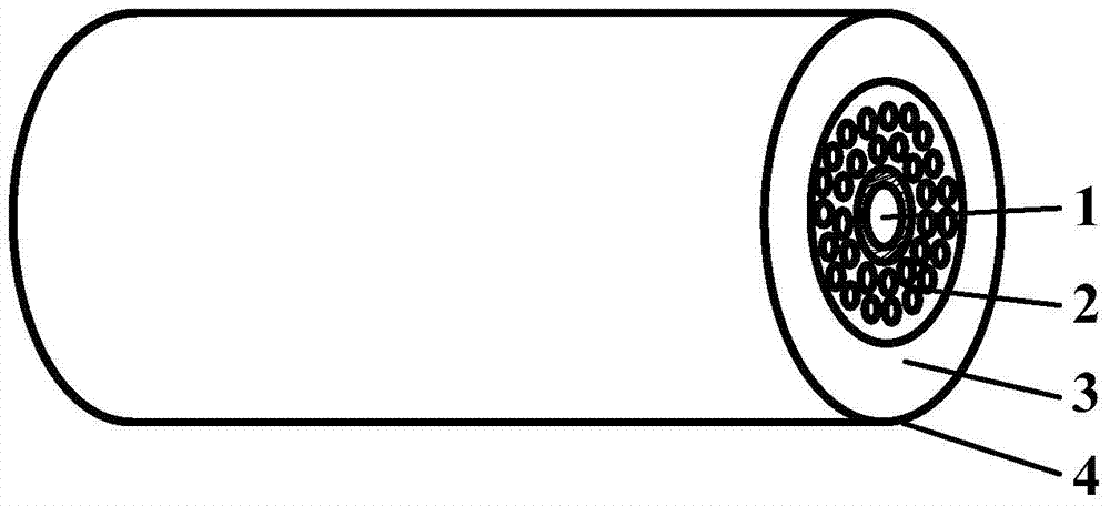
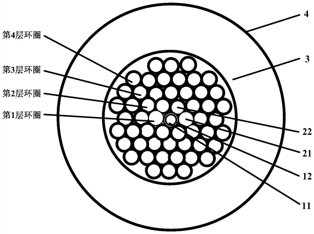
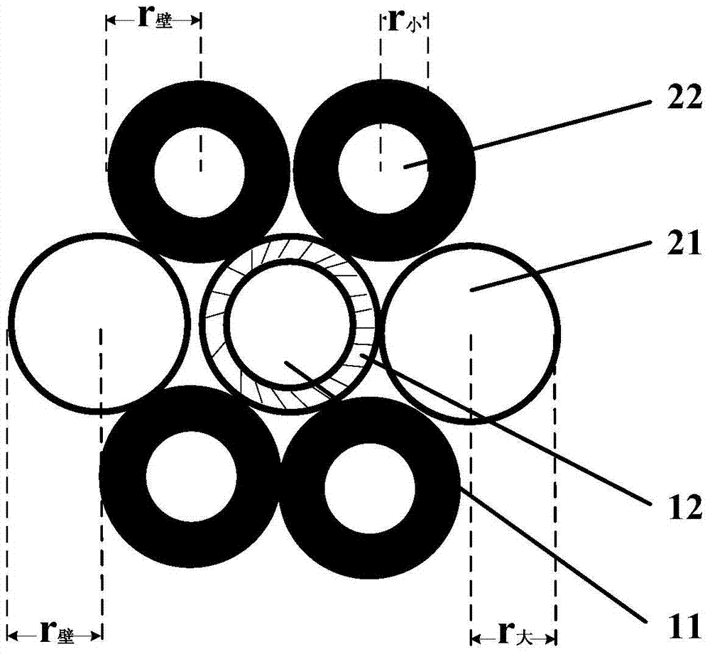
A low-loss radiation-proof birefringent photonic crystal fibre, comprising a central fibre core (1). The central fibre core (1) comprises a pure silicon fibre core (11) and a deep fluorine-doped concave inner cladding (12) coating the outside of the pure silicon fibre core (11). An air pore layer (2) and a quartz cladding (3) successively coat the outside of the central fibre core (1) from inside to outside. The outside of the quartz cladding (3) is coated with a coating layer (4). The air pore layer (2) comprises four layers of rings composed of air pores from inside to outside. The first layer of rings is composed of two large air pores (21) and a plurality of small air pores (22). The second, third and fourth layers of rings are all composed of the plurality of small air pores (22). The air pores of the four layers of rings are all arranged in a regular hexagonal manner. All the air pores are connected by means of a quartz connecting wall. The fibre realizes birefringence, and at the same time has low-loss and radiation-proof performances, and satisfies the usage requirements in special environment application occasions, such as aerospace.

Description

technical field [0001] The invention relates to the field of photonic crystal fibers, in particular to a low-loss anti-irradiation birefringence photonic crystal fiber. Background technique [0002] High birefringent optical fibers are widely used in communication, sensing and other fields. Optical fiber sensing technology with polarization maintaining optical fiber as the core component, especially fiber optic gyroscope technology and fiber optic hydrophone technology have received more attention. Polarization-maintaining fiber has excellent birefringence effect, which increases the difference in propagation constants of the two orthogonal constituent modes HEx11 and HEy11 of the fundamental mode transmitted inside it, and reduces the coupling probability of these two orthogonal modes, thus in It maintains its polarization state well when transmitting linearly polarized light. With the in-depth development from amplitude modulation to phase or polarization state modulatio...

Claims


Application Information

Patent Timeline
Patent Type & Authority Patents(China)
IPC IPC(8): G02B6/02G02B6/036
CPCG02B6/02333G02B6/036G02B6/032
Inventor 罗文勇刘志坚李伟柯一礼赵磊杜城胡福明雷琼杜琨康志文但融
Owner FENGHUO COMM SCI & TECH CO LTD
Learn More