Wet method dedusting device

A technology of wet dedusting and ultrasonic, which is applied in the direction of combination device, separation method, chemical instrument and method, etc., can solve the problems of high equipment cost, complex flue gas composition, high operation risk, etc., and achieve reduction of equipment size and site occupancy, Save equipment investment and power consumption, save the effect of high-voltage electrostatic power supply equipment

Inactive Publication Date: 2016-03-23
FUJIAN LONGKING
View PDF5 Cites 10 Cited by
  • Summary
  • Abstract
  • Description
  • Claims
  • Application Information

AI Technical Summary

Problems solved by technology

[0006] First, although the problem of ultra-clean emission has been solved, no matter what kind of wet high-voltage electrostatic precipitator it is, it uses the electrostatic dust collection principle that the dust is charged and driven to the dust collection plate by electric field force, and its dust collection effect is Affected by the specific dust collection area and the flue gas wind speed, the larger the specific dust collection area, the lower the flue gas wind speed, and the higher the dust collection efficiency, but increasing the specific dust collection area and reducing the flue gas wind speed both make the body structure bulky , takes up more space, and the equipment cost is too high
[0007] Second, any kind of wet high-voltage electrostatic precipitator needs an expensive high-voltage electrostatic power supply and complex high-voltage power supply control equipment due to its dust collection principle. At the same time, it consumes a lot of power and has high operating costs.
[0008] Third, the horizontal metal plate wet electrostatic precipitator is highly corrosive due to the complex composition of the flue gas after wet desulfurization and entrained mist droplets. The internal parts, including the dust collector and discharge electrode, are made of stainless steel. The dust removal efficiency is high, but the equipment cost is further increased. In order to prevent the stainless steel metal plate from being corroded, it is necessary to continuously spray flushing water to form a water film on the components to achieve anti-corrosion and dust removal. The water consumption is huge.
Although part of the flushing water is recycled, due to the large water consumption, the recycling makes the water system equipment more complicated and the cost is higher, and the amount of wastewater discharged to desulfurization recovery is still too high, and it is often difficult to fully recycle
[0009] Fourth, although the horizontal non-metallic plate type or vertical non-metallic tube electrostatic precipitator solves a series of problems caused by the corrosion of the plate, because the plate is a non-metallic material, its conductivity is not good even though measures to enhance conductivity are adopted. It is still far inferior to the metal plate, so the electric field cannot obtain good volt-ampere characteristics, which affects the dust removal efficiency. To obtain the same dust removal efficiency as the metal plate, it is necessary to increase the specific dust accumulation area, and the equipment cost is not low It is better than the metal plate electrostatic precipitator and takes up more space
Moreover, the dust collection plate is made of non-metallic materials. Since the electrostatic dust collection process is easily accompanied by spark discharge, it is easy to cause ablation of the non-metal plate, and even cause fire and combustion, which has a high operational risk

Method used


Image

  • Wet method dedusting device
  • Wet method dedusting device
  • Wet method dedusting device

Examples


Embodiment Construction

[0032] In order to enable those skilled in the art to better understand the solution of the present invention, the present invention will be further described in detail below in conjunction with the accompanying drawings and specific embodiments.

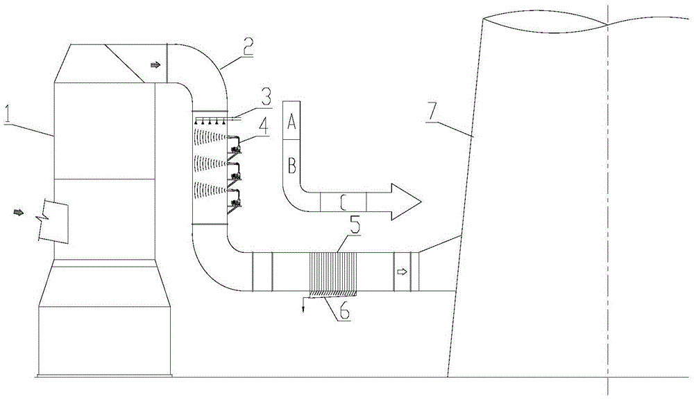
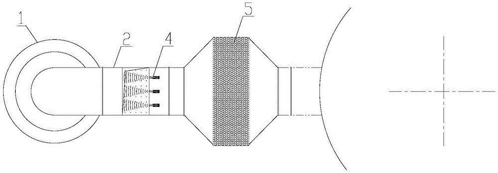
[0033] Please refer to figure 1 , figure 2 , figure 1 It is a structural schematic diagram of a specific embodiment of the wet dust removal device provided by the present invention; figure 2 for figure 1 A top view of the wet scrubber shown.

[0034] In a specific embodiment, the wet dedusting device provided by the present invention is arranged on the flue gas flow channel 2 behind the desulfurization absorption tower 1, and is mainly composed of an ultrasonic atomizer 3, an acoustic wave generator 4, and a droplet catcher 5. and the collection device 6, etc., the flue gas flow channel 2 includes a vertical flow channel and a horizontal flow channel, the ultrasonic atomizer 3 and the sound wave generator 4 are arranged in the...


PUM


Abstract

The invention discloses a wet method dedusting device. The wet method dedusting device comprises a supersonic wave atomizer used for spraying fine water mist towards a smoke flow channel to form a supersonic wave atomization region, a sound wave generator arranged at the lower position of the supersonic wave atomizer according to the smoke flow direction and used for establishing a sound field in the smoke flow channel to form a sound wave coagulation region, and a liquid drop catcher arranged at the lower position of the sound wave generator according to the smoke flow direction used for catching coagulated dust-containing liquid drops after going through the supersonic wave atomization region and the sound wave coagulation region to form a dust collection region. The place occupation, the total cost and operation expenses of the dedusting device after wet method desulphurization can be lowered greatly, waste water discharge of wet method dedusting is reduced, and ultraclean discharge of a chimney is achieved. In addition, because there is no high voltage electrostatic apparatus, internal members can be made of non-conductive corrosion-resistant non-metallic materials, and there are discharge burning operation risks.

Description

technical field [0001] The invention relates to the technical field of dedusting equipment, in particular to a wet dedusting device for combined dedusting of discharged flue gas after wet desulfurization. Background technique [0002] In recent years, with the continuous growth of thermal power installed capacity and the increase in the total amount of pollutants discharged, great pressure has been placed on the atmospheric environment. It was officially implemented on January 1, 2012. [0003] With the promulgation of new standards, people's awareness of fine dust, acid mist, heavy metals and other pollutants harmful to the environment and health has further improved, and the country's emission standards for air pollutants will continue to increase, especially PM2.5. This kind of fine particulate matter, which is extremely harmful to human health, is bound to become the control index of the country's emission standards for air pollutants. However, the existing wet desulfu...

Claims


Application Information

Patent Timeline
Patent Type & Authority Applications(China)
IPC IPC(8): B01D50/00
CPCB01D50/00
Inventor 郑岩峰庄泽杭罗如生林翔黄志杰
Owner FUJIAN LONGKING
Why Eureka
Try Eureka