Indirect coupling conic fiber grating ultrasonic sensor

An ultrasonic sensor and tapered optical fiber technology, applied in the field of sensors, can solve problems such as non-directional recognition, large capacitance influence, interference, etc., achieve good response characteristics, high spectral signal-to-noise ratio, and facilitate real-time acquisition

Inactive Publication Date: 2016-03-23
NORTHWEST UNIV(CN)
View PDF7 Cites 11 Cited by
  • Summary
  • Abstract
  • Description
  • Claims
  • Application Information

AI Technical Summary

Problems solved by technology

However, this device has several shortcomings: it is only sensitive to ultrasonic signals of a specific narrow frequency band; the sensitivity will become weaker as the volume of the transducer decreases and is greatly affected by capacitance; it is extremely susceptible to interference from environmental electromagnetic fields; As the distance between the transmitting source and the receiver increases, it will widen (causing signal distortion); the reusability is poor, and the multi-channel real-time monitoring system is complex; there is no direction recognition, and the ultrasonic direction information cannot be obtained
Therefore, piezoelectric ceramic transducers cannot meet the needs of fine imaging of seismic physical models.

Method used


Image

  • Indirect coupling conic fiber grating ultrasonic sensor
  • Indirect coupling conic fiber grating ultrasonic sensor
  • Indirect coupling conic fiber grating ultrasonic sensor

Examples


Embodiment 1

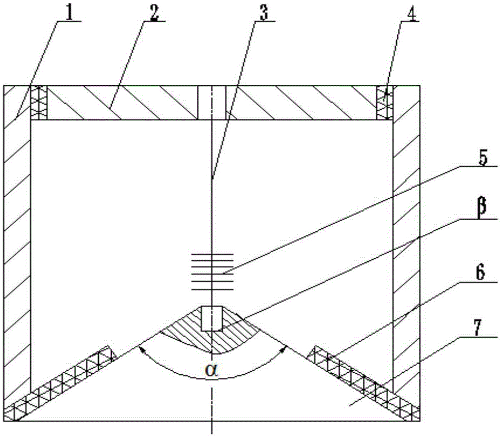
[0016] exist figure 1 Among them, the indirect coupling tapered fiber grating ultrasonic sensor of this embodiment is connected by a housing 1, a cover 2, an optical fiber 3, a cover anechoic pad 4, a grating 5, an acoustic coupling cone anechoic pad 6, and an acoustic coupling cone 7 constitute.

[0017] A cover 2 is bonded to the upper end of the shell 1 with epoxy resin, and a center hole is processed at the center of the cover 2, and a cover is used to silence the sound between the cover 2 and the shell 1. Pad 4, cover The sound-absorbing pad 4 is used to absorb the residual ultrasonic waves in the upper part of the housing 1, and prevent multiple reflections from overlapping to form clutter. The lower end of the housing 1 is bonded with an acoustic coupling cone 7 with epoxy resin, and the acoustic coupling cone muffler pad 6 is bonded between the acoustic coupling cone 7 and the lower end of the housing 1 with epoxy resin, and the acoustic coupling cone muffler pad is ...

Embodiment 2

[0019] In this embodiment, an acoustic coupling cone 7 is bonded to the lower end of the housing 1 with epoxy resin. The diameter of the bottom surface of the acoustic coupling cone 7 is the same as the outer diameter of the housing 1, and the cone angle α of the acoustic coupling cone 7 is 60°. . Other components and the coupling relationship of the components are the same as in Embodiment 1.

Embodiment 3

[0021] In this embodiment, an acoustic coupling cone 7 is bonded to the lower end of the housing 1 with epoxy resin. The diameter of the bottom surface of the acoustic coupling cone 7 is the same as the outer diameter of the housing 1, and the cone angle α of the acoustic coupling cone 7 is 120°. . Other components and the coupling relationship of the components are the same as in Embodiment 1.


PUM


Abstract

The invention relates to an indirect coupling conic fiber grating ultrasonic sensor. According to the indirect coupling conic fiber grating ultrasonic sensor, an upper end of a casing is provided with a sealing cover for processing a center hole, a sealing cover noise abatement pad is arranged between the sealing cover and the casing, a lower end of the casing is provided with a sound coupling cone, a sound coupling noise abatement pad is arranged between the sound coupling cone and the lower end of the casing, the top portion of the sound coupling cone is provided with a light guide fiber mounting hole through processing, one end of a light guide fiber is arranged in the light guide fiber mounting hole, the other end of the light guide fiber penetrates through the center hole of the sealing cover, the light guide fiber is provided with a grating, grating zone length of the grating is 1-10mm, and wavelength is 1540-1560nm. Based on tests, the sensor has excellent response performance, stability and sensitivity for 300KHz wave band ultrasonic signals, under the real-time acquisition mode, the spectrum signal to noise ratio is high, the ultrasonic signals reflected on upper and lower surfaces of organic glass can be intelligibly identified, the ultrasonic signals are suitable for dynamic scanning acquisition in an earthquake physics model, ultrasonic multi-layer imaging can be realized, and the sensor can be applied to the nondestructive structure test, oil and gas field physics model imaging, elastic wave speed modeling and biologic and medical technology fields.

Description

technical field [0001] The invention belongs to the technical field of sensors, and in particular relates to a fiber grating ultrasonic sensor. Background technique [0002] The seismic physical model is a simulated structure reduced in proportion to the geological structure of the reservoir. It can be used as a tool for seismic wave transmission and theoretical prediction. Its biggest advantage is the authenticity of the simulated results, which are not limited by calculation methods and assumptions. Measure the response of sound waves under nearly ideal rock model conditions. Compared with the seismic site, the seismic model built in the laboratory is low in cost, and has good repeatability, stability and controllability. [0003] The ultrasonic sensor is the core device for obtaining the internal information of the earthquake physical model. The fiber optic ultrasonic sensor perceives the intensity, frequency, direction and other information of the ultrasonic transmissi...

Claims


Application Information

Patent Timeline
Patent Type & Authority Applications(China)
IPC IPC(8): G01H9/00
CPCG01H9/004
Inventor 乔学光邵志华荣强周李佳成
Owner NORTHWEST UNIV(CN)
Why Eureka
Try Eureka