Light-stimulated neural electrode device based on golden wire ball bonding method and manufacturing method thereof

A technology of gold wire ball bonding and light stimulation, which is applied in the field of microelectrodes, can solve the problems of troublesome operation, high cost, high requirements for equipment, process and alignment accuracy, and achieve the effect of simple process

Active Publication Date: 2016-03-23
SHANGHAI JIAO TONG UNIV
View PDF8 Cites 11 Cited by
  • Summary
  • Abstract
  • Description
  • Claims
  • Application Information

AI Technical Summary

Problems solved by technology

This method has high requirements on equipment, process and alignment accuracy, high cost and troublesome operation
[0007] In summary, the currently reported LED connection methods have certain defects and limitations in terms of layout flexibility, size applicability, and operating cost.

Method used


Image

  • Light-stimulated neural electrode device based on golden wire ball bonding method and manufacturing method thereof
  • Light-stimulated neural electrode device based on golden wire ball bonding method and manufacturing method thereof
  • Light-stimulated neural electrode device based on golden wire ball bonding method and manufacturing method thereof

Examples


Embodiment 1

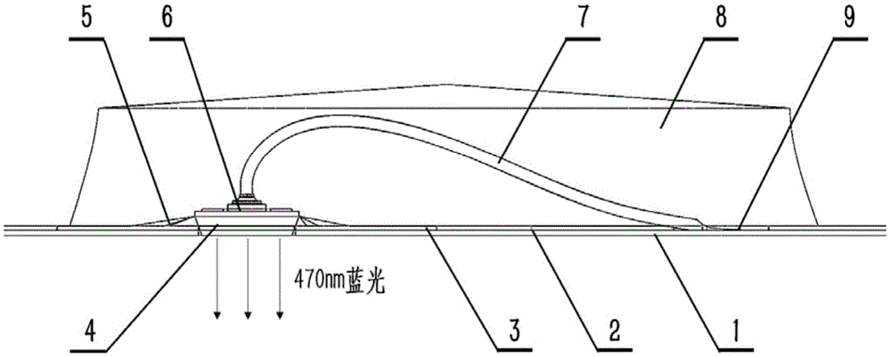
[0039] Such as figure 1 As shown, the present embodiment provides a light-stimulating nerve electrode device based on the gold wire ball bonding method, including: a bottom polyimide insulating layer 1, a gold circuit layer 2, a top polyimide insulating layer 3, a bare micro-LED Chip 4, high temperature resistant instant adhesive 5, gold wire 7, epoxy resin glue 8; wherein: the cathode and anode pads 6 belong to a part of the micro LED bare chip 4, the gold pad 9 belongs to a part of the gold circuit layer 2, and the gold pad 9 belongs to the gold circuit layer 2. The circuit layer 2 is used to supply power to the micro-LED bare chip 4, and the forward voltage is 2.7-3.4V; the bottom polyimide insulating layer 1, the gold circuit layer 2, and the top polyimide insulating layer 3 constitute the main structure of the electrode , the bottom polyimide insulating layer 1 and the top polyimide insulating layer 3 are provided with an overlapping array of square holes for positioning ...

Embodiment 2

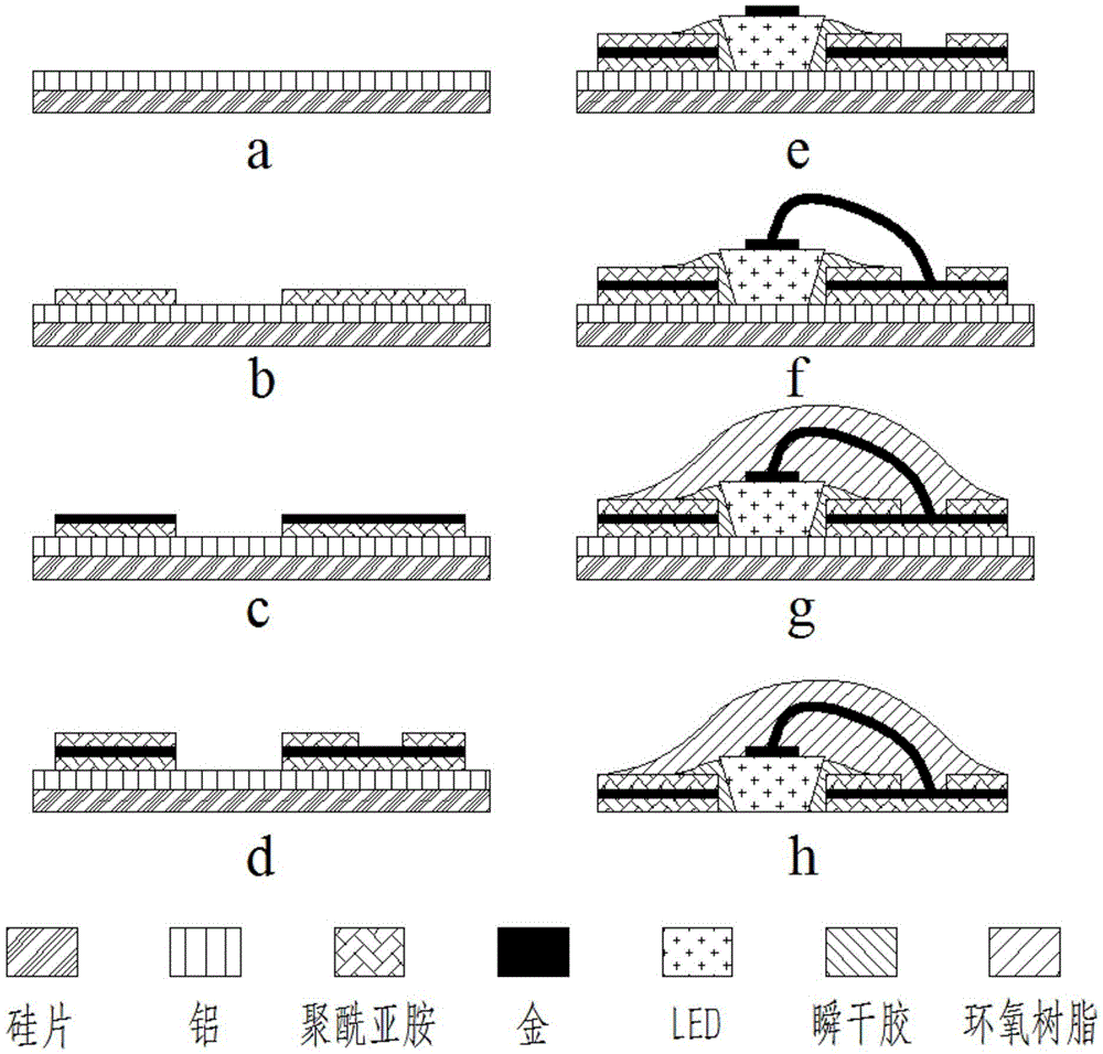
[0056] This embodiment provides a method for preparing a light-stimulating nerve electrode device based on the gold wire ball bonding method similar to that of Embodiment 1, which is prepared according to the following steps:

[0057] 1) Thermally evaporate a layer of 1.0 mm thick aluminum on a 200 micron thick silicon wafer as a sacrificial layer;

[0058] 2) Spin-coat a layer of photosensitive polyimide Durimide7510. After pre-baking, exposure, development and curing, a patterned bottom polyimide insulating layer 1 is produced, with a thickness of 5 microns and 4×4 holes on it. Rectangular hole, the size of the rectangular hole is 205 microns × 255 microns;

[0059] 3) Sputter a layer of chromium and a layer of gold, the thickness of chromium and gold are 50 nanometers and 300 nanometers respectively, spin-coat the positive photoresist AZ4620 with a thickness of 5 microns, and after pre-baking, photolithography, development and post-baking, use Ion beam etching method to ob...


PUM


Abstract

The invention provides a light-simulated neural electrode device based on a golden wire ball bonding method and a manufacturing method thereof. The method comprises steps: 1, a patterned bottom polyimide insulation layer is manufactured, and square holes are opened; 2, a middle circuit layer is manufactured; 3; a patterned top polyimide insulation layer is manufactured, and square holes and round holes are opened at the same positions; 4; a micro LED bare chip is placed in two layers of polyimide square holes, and instantaneous drying glue is applied to the periphery of the micro LED bare chip; 5, by adopting the golden wire ball bonding method, the micro LED bare chip and a golden circuit layer are connected; 6, epoxy resin glue is applied for realizing packaging; and 7, a sacrificial layer is corroded, and electrode release is completed. The electrode device of the invention mainly aims at providing power for the micro LED bare chip, and light emitting by the LED carries out light simulation on an experimental animal with specific gene transfection; and the process is simple, the LED is arranged flexibly, devices of different forms can be manufactured according to different simulation areas, and a new tool is provided for implantable medical device development and neuroscience research.

Description

technical field [0001] The invention relates to a microelectrode in the technical field of biomedical engineering, in particular to a light-stimulating nerve electrode device based on a gold wire ball bonding method and a preparation method thereof. Background technique [0002] In recent years, optogenetics (Optogenetics), as an emerging subject, has received extensive attention from researchers at home and abroad. Optogenetics integrates optical and genetic technologies to precisely control the activities of specific cells in space and time. Its time precision can reach centiseconds, and its spatial precision can reach the size of a single cell. Basic research on mechanisms and therapeutic interventions provides a new bioengineering tool. [0003] The photostimulation devices used in optogenetics can be divided into two categories at present, one is local photostimulation based on optical fiber, and the light source is laser diode or laser; the other is planar photostimul...

Claims


Application Information

Patent Timeline
Patent Type & Authority Applications(China)
IPC IPC(8): H01L33/36A61N5/06
CPCA61N5/0622A61N2005/0651A61N2005/0662H01L33/36
Inventor 刘景全吉博文康晓洋王明浩杨斌陈翔杨春生
Owner SHANGHAI JIAO TONG UNIV
Why Eureka
Try Eureka