Rapid three-dimensional (3D) super-resolution microscopic method and device

A super-resolution and fast technology, applied in the field of super-resolution, can solve the problems of increasing the time complexity of the microscopic system, increasing the space complexity of the optical microscopic system, etc., and achieve the effect of simple device

Inactive Publication Date: 2016-04-13
ZHEJIANG UNIV
View PDF4 Cites 24 Cited by
  • Summary
  • Abstract
  • Description
  • Claims
  • Application Information

AI Technical Summary

Problems solved by technology

[0006] Stimulated fluorescence microscopy has the advantages of low power consumption, weak bleaching, fast imaging, and simple optical path. However, when it is applied to three-dimensional super-resolution microscopy imaging, it is necessary to divide the excitation light into three channels and modulate them separately. T

Method used


Image

  • Rapid three-dimensional (3D) super-resolution microscopic method and device
  • Rapid three-dimensional (3D) super-resolution microscopic method and device
  • Rapid three-dimensional (3D) super-resolution microscopic method and device

Examples


Embodiment Construction

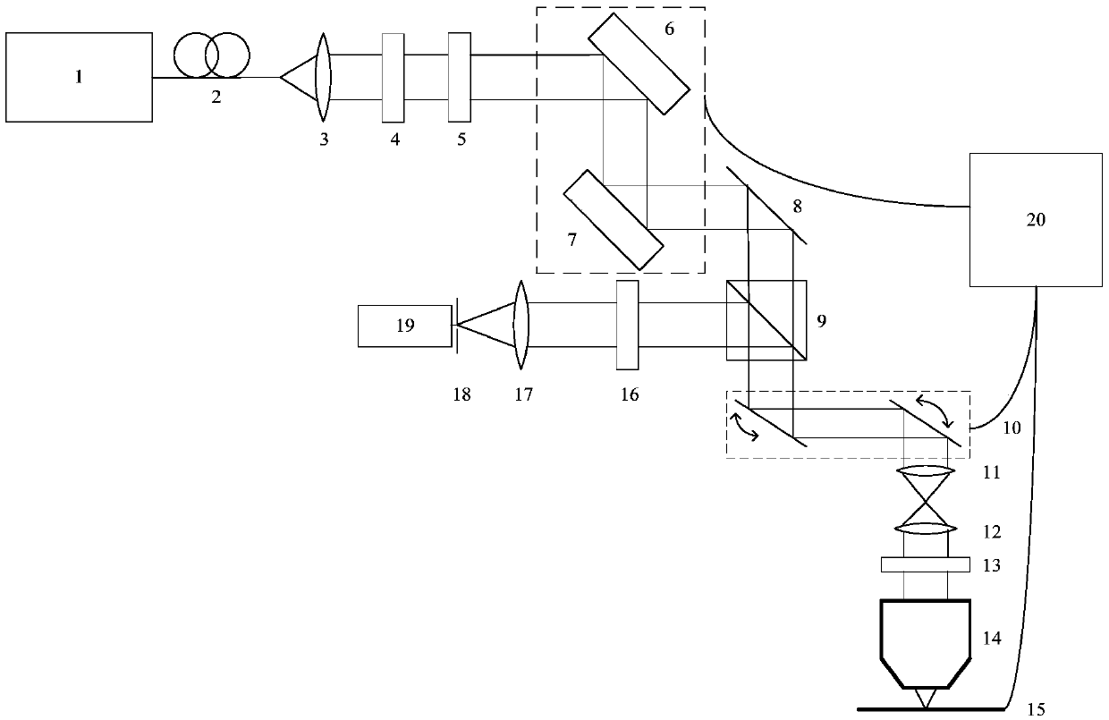
[0050] Such as figure 1 As shown, a fast three-dimensional super-resolution microscopy device, including: laser 1, single-mode fiber 2, collimator lens 3, polarizer 4, 1 / 2 wave plate 5, spatial light modulator 6, spatial light modulation Device 7, mirror 8, beam splitter 9, scanning galvanometer system 10, scanning lens 11, field lens 12, 1 / 4 wave plate 13, microscope objective lens 14, nanometer displacement platform 15, bandpass filter 16, focusing Lens 17, pinhole 18, detector 19 and controller 20.

[0051] Wherein, single-mode fiber 2 , collimator lens 3 , polarizer 4 , half-wave plate 5 and spatial light modulator 6 are sequentially located on the optical axis of the output beam of laser 1 .

[0052] Wherein, the spatial light modulator 7 and the reflector 8 are sequentially located on the optical axis of the light beam modulated by the spatial light modulator 6 .

[0053] Wherein, the beam splitter 9 and the scanning galvanometer system 10 are successively located on t...


PUM


Abstract

The invention discloses a rapid three-dimensional super-resolution microscopic method. The method comprises that a laser beam is converted into linearly polarized light after being collimated, phase modulation is carried out on the linearly polarized light, the linearly polarized light is converted into circularly polarized light, the circularly polarized light is projected to a sample to be measured, and pilot light emitted by scanning points of the sample to be measured is collected; and 3D scanning is carried out on the sample. Phase modulation comprises primary phase modulation and secondary phase modulation, a spatial light modulator which modulates the phase of an s light component of the linearly polarized light is used in the primary phase modulation, a spatial light modulator which modulates the phase of a p light component of the linearly polarized light is used in the secondary phase modulation, and a 3D super-resolution image is obtained according to the effective pilot light intensity. The invention also discloses a rapid 3D super-resolution microscopic device. According to the invention, optical power is lower, the photobleaching effect is weakened, 3D imaging is rapid, the device is simple, and light splitting is not needed.

Description

technical field [0001] The invention belongs to the field of super-resolution, and in particular relates to a method and a device capable of quickly realizing three-dimensional super-diffraction limit resolution in the far field. Background technique [0002] Optical microscopic imaging is a commonly used and effective method for observing submicron microstructures, but the existence of the optical diffraction limit greatly limits the resolution of optical microscopic imaging. According to the principle of Abbe's diffraction limit, the ideal point light source is not an ideal image point after being focused by the microscope objective lens, but a diffraction spot, and its size is determined by the full width at half maximum of the intensity distribution curve of the diffraction spot In the formula, λ is the wavelength of the illumination light used by the microscope, and NA is the numerical aperture of the microscopic objective lens used. Since NA=nsinα, in the formula, n i...

Claims


Application Information

Patent Timeline
IPC IPC(8): G02B21/00G01B11/24
CPCG01B11/24G02B21/0032G02B21/0068
Inventor 刘旭荣子豪赵光远
Owner ZHEJIANG UNIV
Why Eureka
Try Eureka