
Efficient energy-saving and emission-reduction sub-system of automobile

A technology for system temperature and automobile exhaust, which is applied to automobiles with significant energy saving, environmental protection subsystems, and emission reduction fields, and can solve problems such as mixing, waste, and fuel consumption

Inactive Publication Date: 2016-04-20
王树卿
View PDF6 Cites 7 Cited by
  • Summary
  • Abstract
  • Description
  • Claims
  • Application Information

AI Technical Summary

Problems solved by technology

At present, various types of automobiles at home and abroad are common: 1) In the initial driving stage or when the ambient temperature is low, the temperature of the air entering the engine is low, and the atomized fuel is in the state of tiny particles, which cannot be fully mixed with oxygen molecules in the air, that is, poor atomization If it cannot fully burn, the thermal efficiency is low and it is easy to generate carbon deposits, which will affect the life of the engine.
2) The temperature of the system rises slowly, and the thermostat is generally opened from 60°C with an external circulation. When the ambient temperature is lower than 0°C, there is still a problem of overcooling. The temperature is -10°C, driving at a constant speed of 70 kilometers per hour for 1 hour, the system temperature can only reach 61°C
However, the heat source is taken from the coolant of the engine. When the car is first driving or the ambient temperature is low, the system temperature itself is not high. Using it to heat the air entering the engine is not very effective, especially in winter in northern my country. The temperature is often as low as -20°C, and it takes more than 15 minutes to heat up the car at idling speed to 40°C, and this warm-up stage requires a thicker mixture and consumes a lot of fuel, especially for buses with heating functions. Fuel consumption is used to support heating, at the same time, the heat energy of the exhaust gas is not used and wasted
The invention patent application document with the patent number 201410073161.3 discloses a subsystem for energy saving and emission reduction by using exhaust heat from automobile exhaust to increase air temperature and system operating temperature. And its storage box, waste heat collector, booster fan, electric proportional valve for switching waste heat or hot "coolant" two heat sources and changing the "single circuit" air heat exchanger into a "double circuit" heat exchanger, using Exhaust gas waste heat is used to increase the air temperature and system working temperature, which solves the problem that the patent No.: 201310325748.4 is not effective in the initial driving stage of the car and when the ambient temperature is low. This invention patent is especially suitable for low ambient temperature and heating function of public transport vehicles
The fly in the ointment of the above two invention patents is: when the ambient temperature is high and there is a large power demand, the air heat exchanger has "thermal inertia", and the power boost time is slightly longer; Put space and can't install problem

Method used


Image

  • Efficient energy-saving and emission-reduction sub-system of automobile
  • Efficient energy-saving and emission-reduction sub-system of automobile
  • Efficient energy-saving and emission-reduction sub-system of automobile

Examples


Embodiment Construction

[0013] The present invention has three combinations:

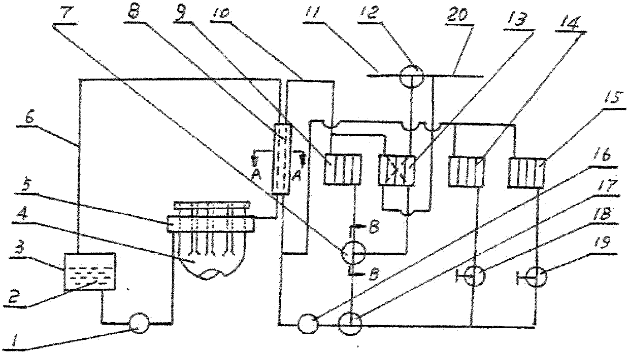
[0014] The first type: Vehicles without the whole vehicle heating function: consisting of liquid pump 1, heat transfer medium 2, storage box 3, waste heat collector 5, coolant heat exchanger 8, electric three-way proportional valve 7, double-circuit air heat exchange 13, electromagnetic three-way valve 12, condenser and its fan 14 (note: original car parts), electric ball valve 18, relay ①, relay ②, temperature adjustment module ECU, gear switch, temperature digital display. 10 seconds after the engine is started, the system temperature measured by the coolant temperature sensor (which can be shared with the original car) is lower than 84°C and maintained for 10 seconds, the liquid pump 1 starts to rotate, and the heat transfer medium 2 flows through the liquid pump from the storage box 3 1. The waste heat collector 5 and the coolant heat exchanger 8 return to the storage box 3, and the waste heat collected by the waste he...


PUM


Abstract

The invention relates to an efficient energy-saving and emission-reduction sub-system of an automobile and belongs to the technical field of machine manufacturing. By utilizing a method of recycling waste heat of tail gas of an automobile engine and controlling external circulation flow of a cooling liquid, the temperature of a system is raised to about 84-87 DEG C as far as possible and is kept; and by controlling the flow of the cooling liquid flowing through an air heat exchanger, the temperature of air entering the engine is raised and regulated to 56-75 DEG C. When the engine is in the two temperature states, fuel oil molecules are in single molecule states and can be sufficiently mixed with oxygen molecules in the air to be sufficiently combusted, thus achieving energy saving and emission reduction. When system temperature reaches 86 DEG C, a liquid pump stops rotation to stop recycling of the waste heat; and a proportional valve distributes the cooling liquid to the air heat exchanger to raise and regulate temperature of the air. When extra requirement for power is available, temperature regulation on air is stopped, and when throttle percentage reaches more than 60%, pressurizing is performed and the air is quickly cooled by utilizing cold air. In warming-up at idle speed, air-fuel ratio is gradually increased to 15.6-15.9 from 14.7 in three times.

Description

Technical field: [0001] The invention belongs to the technical field of machinery manufacturing, and relates to a sub-system with significant energy saving, emission reduction and environmental protection for automobiles. Background technique: [0002] In today's era when people are pursuing convenience, speed, and developed transportation, automobiles have become an important and widely used means of transportation at home and abroad. As far as China alone is concerned, there are more than 200 million automobiles in use. There are 20 million cars produced, and these fuel-fueled vehicles consume about 500 million tons of fuel every year, worth about 5 trillion yuan. However, the data show that the proven oil reserves in the world are only enough for about one hundred years. Now in the stage of global energy shortage, especially in my country, the situation is even more serious: that is, my country is a big importer of oil, and about half of the oil will rely on imports. So...

Claims


Application Information

Patent Timeline
Patent Type & Authority Applications(China)
IPC IPC(8): F01N5/02F02N19/10F02M31/10F02B29/04F01P7/14F01P7/16F01P7/08B60H1/04F02B33/40F02D41/06
CPCB60H1/04F01N5/02F01P7/08F01P7/14F01P7/165F01P7/167F01P2007/146F01P2037/02F01P2060/02F01P2060/08F02B29/0443F02B33/40F02D41/064F02D2250/32F02M31/10F02N19/10Y02T10/12Y02T10/88
Inventor 王树卿
Owner 王树卿
Learn More