Sealing composition
A technology for sealing and composition, which is applied in the direction of electrical components, circuits, electroluminescent light sources, etc., and can solve problems such as deterioration of organic EL components
- Summary
- Abstract
- Description
- Claims
- Application Information
AI Technical Summary
Problems solved by technology
Method used
Image

Examples
Embodiment 1
[0232] Put 60 parts by weight of compound (a-1), 40 parts by weight of compound (d-1), 2 parts by weight of photocationic polymerization initiator (b-1) and 0.4 parts by weight of curing retarder (c-1) into the rotation and revolution mixing (trade name "Awa-toriRentaro (あわとり入太郎) ARE-310", manufactured by Thinky Co., Ltd.) and stirred to obtain a sealing composition (1) (viscosity: 265 mPa·s).
[0233] The obtained sealing composition (1) was coated on a glass substrate to form a coating film (1) (thickness: 100 μm), and ultraviolet rays were irradiated with a mercury lamp (irradiation amount: 1600 mJ / cm 2 ).
[0234] The viscosity immediately after ultraviolet irradiation was 892 mPa·s, and the viscosity 30 minutes after ultraviolet irradiation was 4540 mPa·s.
[0235] Then, the coating film (1) after ultraviolet irradiation was heated at 100°C for 1 hour to obtain a cured product (1) having a curing degree of 50% or more.
[0236] With respect to the obtained cured product...
Embodiment 2~10、 comparative example 1~5
[0238] Except having changed the formulation as shown in the following table, it carried out similarly to Example 1, obtained the composition for sealing, obtained the coating film, and obtained the hardened|cured material (hardening degree 50% or more).
[0239] With respect to the obtained cured product, the gas discharge rate and water vapor permeability were evaluated by the following methods.
[0240]
[0241] The exhaust gas (unit: ppm) derived from the curing retarder of the cured products obtained in Examples and Comparative Examples was measured as follows: 60 mg of cured products were added to a vial, and UV irradiation (2000 mJ / cm 2 ), and left to stand at 100° C. for 1 hour, and then measured the exhaust volume in the vial. Here, a calibration curve was prepared using a toluene standard solution [toluene as a standard substance: 100 ppm, solvent: hexane (60 mg)]. In addition, as a measurement device, a product name "HP-6890N" (manufactured by Hewlett-Packard Co....
Embodiment 11
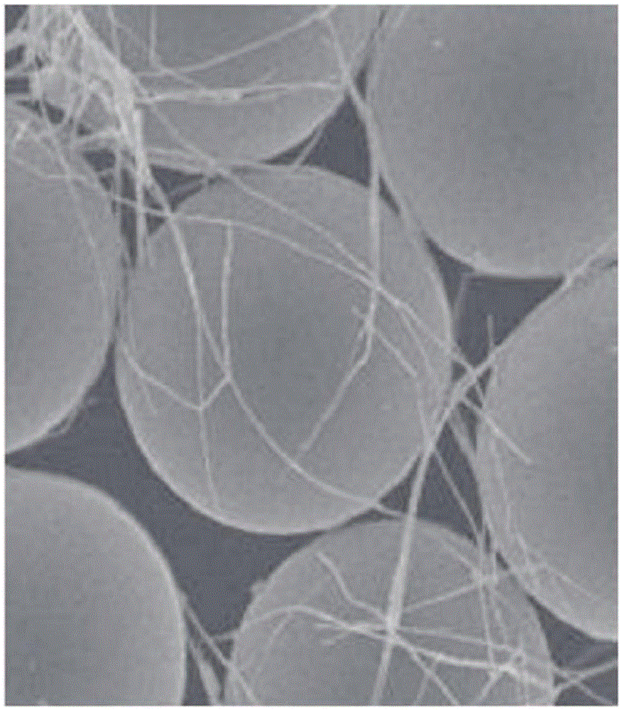
[0246] (Manufacture of conductive fiber-coated particles)
[0247] Particulate matter (plastic particles, trade name "TechpolymerSM10X-8JH", methyl methacrylate styrene copolymer, manufactured by Sekisui Chemical Co., Ltd., 10% compressive strength: 2.5kgf / mm 2 , average particle diameter 8.3 μm, refractive index: 1.565) 0.15 parts by weight and 29.15 parts by weight of 2-butanol were mixed to prepare a dispersion of particulate matter.
[0248] 5.22 parts by weight of a dispersion of silver nanowires (manufactured by Aldrich, average length: 20-50 μm, average diameter: 115 nm) (0.15 parts by weight of silver nanowires) was mixed with the dispersion of the obtained particulate matter, and then filtered through The solvent was removed to obtain conductive fiber-coated particles (1) [the surface area (total surface area) of the plastic particles / projected area (total projected area) of the silver nanowires was calculated, and the result was about 100 / 15].
[0249] The obtained ...
PUM
 Abstract
Description
Claims
Application Information
 - R&D
- Intellectual Property
- Life Sciences
- Materials
- Tech Scout
- Unparalleled Data Quality
- Higher Quality Content
- 60% Fewer Hallucinations
Browse by: Latest US Patents, China's latest patents, Technical Efficacy Thesaurus, Application Domain, Technology Topic, Popular Technical Reports.
© 2025 PatSnap. All rights reserved.Legal|Privacy policy|Modern Slavery Act Transparency Statement|Sitemap|About US| Contact US: help@patsnap.com