
Double-frequency circularly polarized antenna

A circularly polarized antenna and low-frequency technology, which is applied to antennas, slot antennas, and devices that enable antennas to work in different bands at the same time, can solve the problems of large antenna physical size, low yield, and large feed network loss, etc., to achieve The effect of high radiation efficiency and simple structure

Active Publication Date: 2016-05-18
NO 54 INST OF CHINA ELECTRONICS SCI & TECH GRP
View PDF5 Cites 8 Cited by
  • Summary
  • Abstract
  • Description
  • Claims
  • Application Information

AI Technical Summary

Problems solved by technology

[0003] 1. Waveguide slot antenna: This type of antenna is slotted on the wide or narrow side of the waveguide. Usually, there are two array forms of traveling wave and standing wave, but the gain of the radiating unit slot is relatively low, usually only about 7dB. In the form of series feed, there is a frequency sweep phenomenon within the bandwidth. With the increase of the working frequency, the processing accuracy is required to be higher, and it needs to be processed and manufactured with the help of a higher welding process. Polarized co-aperture radiation is more difficult
[0004] 2. Microstrip patch antenna, which has a low profile, can integrate active devices, and can realize the integrated design of the radiation unit and the network, but the dielectric loss of the antenna is large, and there is a leaky wave effect, and the gain of the antenna unit is low , Feed network loss is large, do not use to achieve high-gain antenna design
[0005] 3. Reflecting surface antenna, this type of antenna has good radio frequency performance in the Ka frequency band, low loss, high radiation efficiency, and relatively simple technology to achieve circular polarization radiation, but this type of antenna has a large physical size and is not suitable for some Where space is limited
[0006] 4. Lens antenna, the form of the antenna is similar to that of the reflector antenna. Usually, the feed source is used to irradiate the dielectric ball, the dielectric cake, etc. to focus the beam and achieve the purpose of high-gain irradiation. However, the same antenna size as the reflector antenna is too large. The function of beam adjustment cannot be realized

Method used


Image

  • Double-frequency circularly polarized antenna
  • Double-frequency circularly polarized antenna

Examples


Embodiment Construction

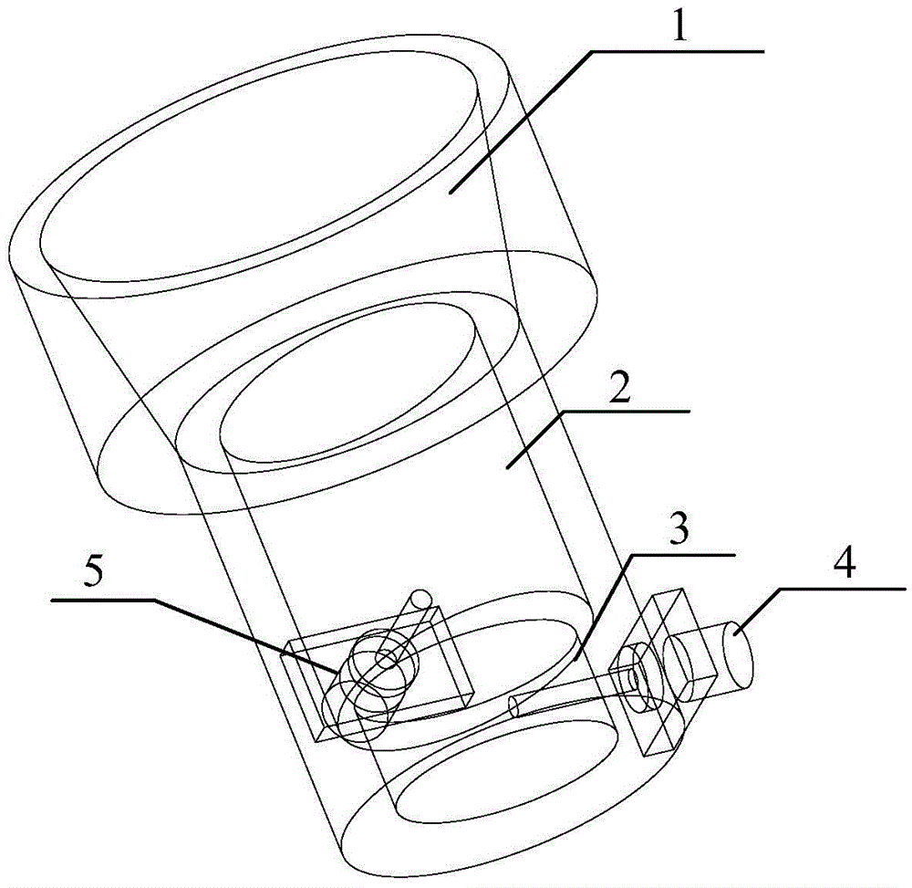
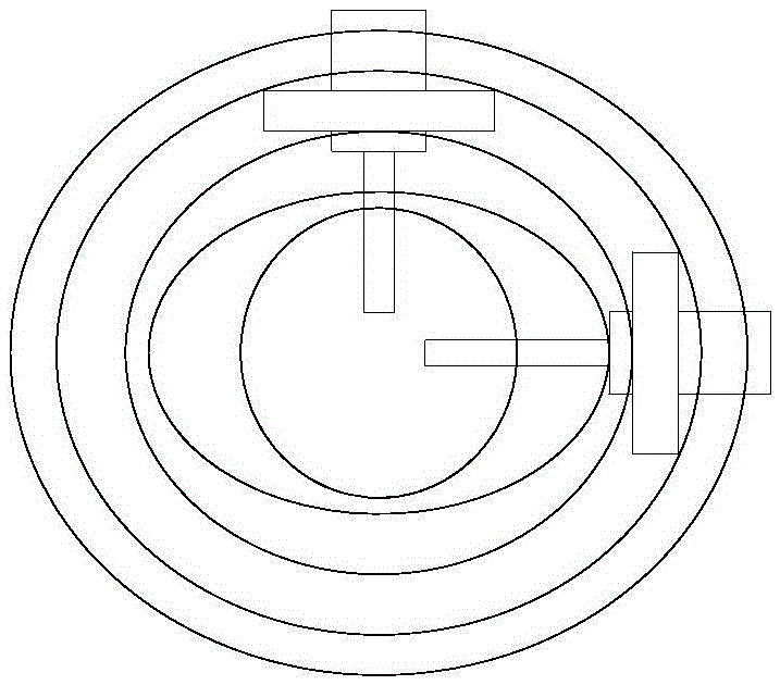
[0019] refer to figure 1 , figure 2 , the present invention is composed of a conical bell mouth 1, a low-frequency resonant cavity 2, a high-frequency resonant cavity 3, a high-frequency polarization probe 4 and a low-frequency polarization probe 5, figure 1 is a schematic diagram of the three-dimensional structure of the present invention, figure 2 It is an internal perspective schematic diagram of the present invention, which shows the relative positional relationship and internal structural composition of each component.

[0020] The conical horn mouth 1 is located on the uppermost layer, and its function is to receive and transmit electromagnetic signals, and realize the design of the pattern according to certain spatial power beam coverage requirements. The present invention adopts a gradual conical horn to ensure the impedance matching between the resonant cavity and the horn mouth. Usually, the diameter of the radiation port of the cone horn mouth is taken as its ap...


PUM


Abstract

The invention discloses a double-frequency circularly polarized antenna, which comprises, from top to bottom, a cone-shaped bell mouth, a low frequency resonant cavity, and a high frequency resonant cavity sequentially. The side wall of the low frequency resonant cavity and the side wall of the high frequency resonant cavity are fixedly provided with a low frequency polarized probe and a high frequency polarized probe respectively and correspondingly. The two resonant cavities are respectively in the shape of an elliptic cylinder, and the elliptical long axes are respectively and correspondingly collinear with the probes. The projections of the elliptical long axes of the two resonant cavities on the interface of the two resonant cavities are vertical to each other. The antenna provided by the invention is advantageous in that the impedance bandwidth is greater than 20%, the bandwidth inner gain is greater than 8.5 dB, the radiation efficiency is greater than 81.5%, the axis ratio bandwidth smaller than 3dB is greater than 25%, and the port isolation bandwidth is greater than 30%, and the central frequency of the double-frequency end is 1.5; the structure of the whole antenna is simple and compact, and the radio efficiency is high; the double-frequency circularly polarized radiation is adopted, and the antenna can be used as the plane array radiation unit, and therefore the high efficiency narrow wave beam radiation can be realized.

Description

technical field [0001] The invention relates to a high-efficiency circularly polarized array antenna in the field of satellite communication and microwave communication. The antenna design technology mainly includes: common aperture dual-frequency circular polarization technology and high isolation technology. Background technique [0002] At present, the communication frequency band is more and more developing towards the high frequency band, especially in the Ku and Ka bands. The frequency determines the bandwidth ratio of the antennas working in the L and S bands. The antennas required to work in this frequency band have small size, high gain, and spot beams. In particular, the distance between the transmitting and receiving working frequency bands is relatively long, the antenna needs dual-frequency operation, and circularly polarized radiation is required. The antennas that achieve the above performance mainly include the following types of antennas, but each has its own...

Claims


Application Information

Patent Timeline
Patent Type & Authority Applications(China)
IPC IPC(8): H01Q1/36H01Q13/18H01Q5/10H01Q5/28
CPCH01Q1/36H01Q13/02H01Q13/18
Inventor 宋长宏
Owner NO 54 INST OF CHINA ELECTRONICS SCI & TECH GRP
Learn More