A method and device for simultaneous decolorization and nitrogen recovery of printing waste liquid

A recovery device and waste liquid technology, which is applied in the field of textile printing and dyeing industry, can solve the problems of secondary pollution, easy formation of brackish water, increase investment in treatment system infrastructure, etc., and achieve the effect of preventing secondary pollution and low moisture content of sludge

Active Publication Date: 2019-01-25
QINGDAO UNIV
View PDF8 Cites 0 Cited by
  • Summary
  • Abstract
  • Description
  • Claims
  • Application Information

AI Technical Summary

Problems solved by technology

However, the coagulation method and acid precipitation method can only remove water-soluble acrylic resins, pigments and other organic substances in the waste liquid, but cannot remove the ammonia nitrogen in the waste liquid at the same time. Usually, other chemical or biological methods are required for separate nitrogen removal, such as Chemical precipitation method, stripping method, biological denitrification, etc., increase investment in treatment system infrastructure
Especially the acid analysis method directly adds inorganic acid to the waste liquid, which increases the content of acid radical ions in the waste water, causes secondary pollution, and easily forms brackish water

Method used


Image

  • A method and device for simultaneous decolorization and nitrogen recovery of printing waste liquid
  • A method and device for simultaneous decolorization and nitrogen recovery of printing waste liquid
  • A method and device for simultaneous decolorization and nitrogen recovery of printing waste liquid

Examples


Embodiment Construction

[0036] Reference figure 1 , figure 2 , image 3 with Figure 4 .

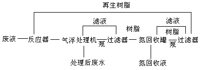
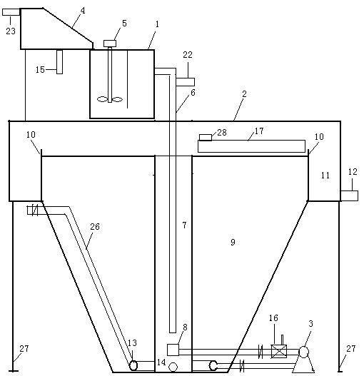
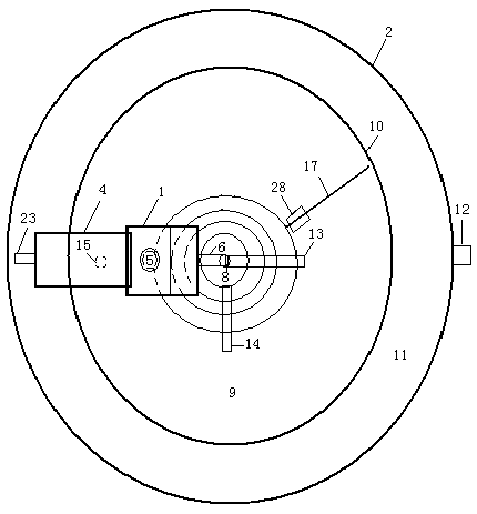
[0037] The invention provides a synchronous decolorization and nitrogen recovery device for ink printing waste liquid, which comprises a reactor 1, an air flotation processor 2, 1 # Filter 19 and 2 # Filter 4 and nitrogen recovery tank 20.

[0038] The reactor 1 is divided into 2 compartments, the bottom is open and connected, the first compartment reaction tank is equipped with a stirrer 5, and the upper part of the second compartment reaction tank is provided with a liquid guide 6 connected to the air flotation treatment machine, the diameter of the guide tube is 20cm , The reactor 1 is located on the upper part of the air flotation processor 2.

[0039] The air flotation treatment machine 2 includes a contact separation chamber 7, a return water pump 3, an air flotation separation chamber 9, and a sludge tank 11;

[0040] The contact separation chamber 7 of the air flotation treatment machine is cylindrical, and t...


PUM

PropertyMeasurementUnit
diameteraaaaaaaaaa
widthaaaaaaaaaa
depthaaaaaaaaaa

Abstract

The invention discloses a printing waste liquid synchronous decolorization and nitrogen recovery method and device. The device comprises a reactor, a floatation treatment machine, filters and a nitrogen recovery tank, wherein the floatation treatment machine comprises a contact separation chamber, a floatation separation chamber, a return water pump, a sludge scraper, a perforated collector pipe and a sludge sump, wherein a return water pipe is arranged between the floatation machine contact separation chamber and the floatation separation chamber; the return water pipe is provided with the return water pump and an ejector; a resin discharge pipe is arranged between the floatation machine contact separation chamber and the filter, and provided with a resin discharge pump; the filter is positioned above the nitrogen recovery tank; the filter is arranged between the nitrogen recovery tank and the reactor; a resin discharge pipe is arranged between the nitrogen recovery tank and the filter, and provided with a sludge pump; and the filter is positioned above the reactor. By using the treatment method and treatment device, the decolorization rate of the high-concentration printing waste liquid is up to 99.5% or above, the ammonia nitrogen removal rate reaches 90% or so, and the CODCr removal rate reaches 90% or above, thereby implementing synchronous decolorization and nitrogen recovery on the waste liquid. By using the method and device, the water content of the sludge is lowered on the premise of not increasing the acid ion content in the wastewater.

Description

Technical field [0001] The invention belongs to the technical field of textile printing and dyeing industry, and particularly relates to a method and device for synchronous decolorization and nitrogen recovery of ink printing waste liquid. Background technique [0002] At present, a large number of plastic packaging (waterproof) materials are increasingly using water-based inks when printing, and a certain amount of high-concentration water-based ink waste liquid is generated during the production process. Although the amount of the ink waste liquid is small, the waste liquid contains high-concentration pigments, water-soluble acrylic resins, alcohols, amines (ammonia) and other pollutants. It has high organic content, high chroma, high nitrogen content, and extremely serious pollution. (Chroma: more than 30,000 times; COD Cr : 100,000-500,000 mg / L; ammonia nitrogen: 1,000-5,000 mg / L), difficult to handle. Most companies adopt the method of pretreatment by physical and chemical ...

Claims


Application Information

Patent Timeline
Patent Type & Authority Patents(China)
IPC IPC(8): C02F9/04C02F103/30C02F101/16
CPCC02F1/001C02F1/24C02F1/42C02F9/00C02F2001/425C02F2101/16C02F2103/30C02F2301/08
Inventor 柳荣展张宾邹译慧潘颖张晓东于梦楠
Owner QINGDAO UNIV
Why Eureka
Try Eureka