Solar cell structure

A solar cell and electrode technology, applied in circuits, electrical components, semiconductor devices, etc., can solve the problems of few carrier transport and absorption improvements, increase external quantum efficiency, increase light utilization, The effect of weight reduction

Inactive Publication Date: 2016-06-15
BEIHANG UNIV
View PDF0 Cites 1 Cited by
  • Summary
  • Abstract
  • Description
  • Claims
  • Application Information

AI Technical Summary

Problems solved by technology

Few improvements in carrier transport and absorption have been enhanced by optical design

Method used


Image

  • Solar cell structure
  • Solar cell structure
  • Solar cell structure

Examples


Embodiment Construction

[0018] Embodiments of the present invention will be described in detail below with reference to the accompanying drawings.

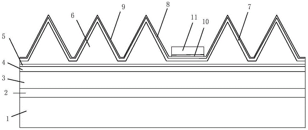
[0019] Such as figure 1 As shown, the present invention provides a solar cell structure, comprising: a back electrode 2, a buffer layer 3, a background layer 4, a reflection layer 5, a base layer 6, an emission layer 7, a window layer 8, Anti-reflection layer 9, contact layer 10 and gate line electrode 11; Wherein, described base layer 6 comprises first base layer and second base layer, and described second base layer is positioned on described first base layer, and the shape of described second base layer Convex in the shape of multiple side-by-side triangular prisms. Preferably, the contact layer 10 and the gate line electrode 11 are located in the depression between the triangular prism-shaped protrusions on the anti-reflection layer 9 . Wherein preferably, the contact layer 10 and the grid line electrode 11 are located in the recesses separated by ...


PUM


Abstract

The invention relates to a solar cell structure, comprising: a back electrode, a buffer layer, a background layer, a reflection layer, a base layer, an emission layer, a window layer, an anti-reflection layer, a contact layer and a grid line electrode formed sequentially on a substrate; , the base layer includes a first base layer and a second base layer, the second base layer is located on the first base layer, and the shape of the second base layer is a plurality of side-by-side triangular column-shaped protrusions. By adopting the solar cell structure provided by the present invention, the base layer is set in the shape of a triangular prism, which not only reduces the thickness of the base layer, but also reduces the thickness and weight of the battery, increases the length of light absorption, and increases the utilization of light The rate increases the external quantum efficiency, reduces the recombination of carriers, increases the internal quantum efficiency of the solar cell, and improves the conversion efficiency of the solar cell.

Description

technical field [0001] The invention relates to the technical field of solar cell power generation, in particular to a solar cell structure. Background technique [0002] Existing types of solar cells include: monocrystalline silicon, polycrystalline silicon, amorphous silicon, III-V compounds, II-VI compounds, copper indium gallium selenide, copper zinc tin sulfur, dye-sensitized, organic and other solar cells. Most of these solar cells are layered and planarly stacked. Starting from the substrate, each layer is grown flat or evaporated onto another layer. Except for grid line electrodes and light trapping designs, there is basically no uneven design. . Each layer is composed of cuboids, the battery is relatively thick and heavy, and the carriers generated by the excitation of sunlight in the working area will recombine when they move to the back electrode and grid electrode, and the battery efficiency is not high. [0003] At present, the improvement of solar energy effi...

Claims


Application Information

Patent Timeline
Patent Type & Authority Applications(China)
IPC IPC(8): H01L31/0352
CPCH01L31/0352
Inventor 段晓旭何云涛
Owner BEIHANG UNIV
Why Eureka
Try Eureka