
D-axis and A-axis current vector composite controller of permanent-magnet synchronous motor

A technology of permanent magnet synchronous motor and compound controller, which is applied in motor control, vector control system, motor generator control, etc., and can solve the high requirements for the accuracy, real-time performance and processing speed of rotor position and current detection and calculation , Control gain affects system stability, affects system control performance and other issues

Active Publication Date: 2016-06-15
TSINGHUA UNIV
View PDF5 Cites 20 Cited by
  • Summary
  • Abstract
  • Description
  • Claims
  • Application Information

AI Technical Summary

Problems solved by technology

This control method that only uses error feedback to adjust requires the output to change and form a deviation before it can form a deviation correction control, which limits the dynamic performance of the system. At the same time, too high a control gain will also affect the stability of the system.
The above vector control method has high requirements on the detection and calculation accuracy, real-time performance and processing speed of the rotor position and current.
In particular, when the current signal detected in real time is disturbed, it will directly affect the control performance of the system

Method used


Image

  • D-axis and A-axis current vector composite controller of permanent-magnet synchronous motor
  • D-axis and A-axis current vector composite controller of permanent-magnet synchronous motor
  • D-axis and A-axis current vector composite controller of permanent-magnet synchronous motor

Examples


Embodiment Construction

[0022] The present invention will be further described below using the accompanying drawings and embodiments. The accompanying drawings described here are used to provide a further understanding of the present invention, constitute a part of the present application, and do not constitute a limitation to the present invention.

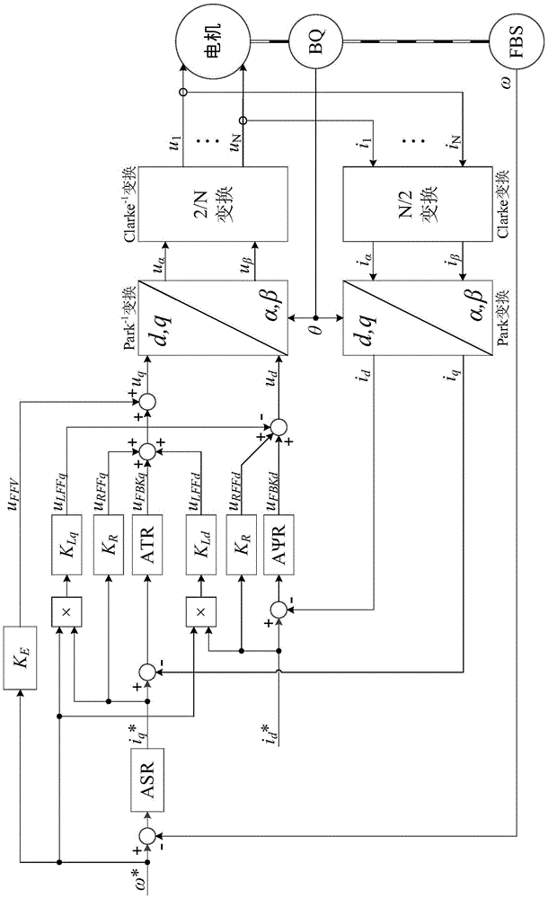
[0023] This embodiment takes a three-phase permanent magnet synchronous motor as an example, including U, V, and W three-phase windings, and the phase difference between any two phases is 120°. The rotary transformer is used as the rotor position sensor, and the angular velocity of the rotor is obtained at the same time. Three-phase stator currents are measured with integrated conductor Hall effect sensors. Speed ​​given signal ω * Timed transmission to the controller by the external digital bus. The controller adopts the TMS320C28x of Texas Instruments (TI) TM A series of digital signal processing chips, which contain a timing interrupt source, and ...


PUM


Abstract

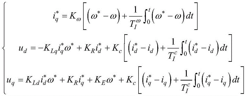
The invention relates to a D-axis and A-axis current vector composite controller of a permanent-magnet synchronous motor. The D-axis and A-axis current vector composite controller is characterized by comprising a position sensor, a speed measurement feedback link, a counter potential feed-forward compensator, a rotational speed closed-loop controller, an A-axis current composite controller, a D-axis current composite controller and a vector converter. By the D-axis and A-axis current vector composite controller, decoupling composite control is separately carried out on i<d> and i<q> under a dq coordinate, the speed regulation range is wide, phase shift of a phase current closed-loop control structure caused by limited bandwidth of the controller is prevented, and the D-axis and A-axis current vector composite controller has favorable performance in all ranges of speed regulation; through the adoption of a composite controls structure with combination of feed-forward and feedback, the dynamic characteristic is improved, the feedback control gain is reduced, and the gain margin of the system is improved; feed-forward is designed on the basis of the dynamic characteristic of an object, and D-axis and A-axis current vector composite controller is clear in physical concept, simple in structure and stable in working, and is easy to be implemented; and meanwhile, feedback control is introduced, the control precision is improved, and an error caused by model inaccuracy and disturbance is overcome.

Description

technical field [0001] The invention belongs to the technical field of motor control, and relates to a method for compound control of orthogonal axis current vectors of a permanent magnet synchronous motor. This method is suitable for the control of high-precision electric servo system in aerospace, military equipment and industrial production. Background technique [0002] The current vector control method used in the high-precision electromechanical servo system needs to accurately detect the rotor position angle θ and the stator current of each phase in real time, and realize the direct-axis current i by establishing the dq-axis mathematical model of the motor. d and quadrature current i q decoupling control. The commonly used current closed-loop vector control has two basic structures: the current control based on the stator reference frame and the current control based on the rotor reference frame. [0003] Based on the current control structure of the stator referen...

Claims


Application Information

Patent Timeline
Patent Type & Authority Applications(China)
IPC IPC(8): H02P21/22H02P21/18
CPCH02P21/14H02P2205/01H02P2205/07H02P2207/05
Inventor 和阳朱纪洪
Owner TSINGHUA UNIV
Learn More