High-energy-efficiency low-jitter single loop clock data recovery circuit

A clock data recovery, low jitter technology, applied in the direction of electrical components, automatic power control, etc., can solve the problems of increasing power consumption and design complexity, phase deviation, affecting the jitter performance of the clock data recovery circuit, and improving the jitter performance. , the effect of reducing area burden and design complexity, reducing the number of polyphase clocks and overall power consumption

Active Publication Date: 2016-06-22
INST OF ADVANCED TECH UNIV OF SCI & TECH OF CHINA
View PDF5 Cites 36 Cited by
  • Summary
  • Abstract
  • Description
  • Claims
  • Application Information

AI Technical Summary

Problems solved by technology

This structure avoids the maximum frequency limit that the on-chip clock can achieve, and greatly saves the power consumption of the 1/N rate structure; however, the clock data recovery circuit of the traditional 1/N rate structure needs to provide 2N multi-phase clocks for 1/N The N-rate pha...

Method used


Image

  • High-energy-efficiency low-jitter single loop clock data recovery circuit
  • High-energy-efficiency low-jitter single loop clock data recovery circuit
  • High-energy-efficiency low-jitter single loop clock data recovery circuit

Examples


Embodiment Construction

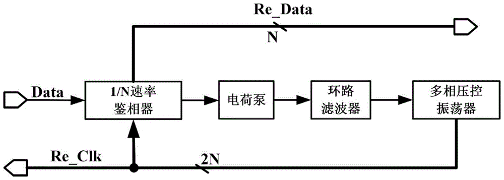
[0031] refer to Figure 4 , a high-energy-efficiency and low-jitter single-loop clock data recovery circuit proposed by the present invention includes: a phase detector, a voltage-current converter, a loop filter and a multi-phase clock generator. Wherein, the phase detector adopts a 1 / N rate Bang-Bang phase detector, which includes a 1:N splitter functional module.

[0032] The first input terminal of the phase detector is connected to the input data DATA, its output terminal is connected to the voltage-current converter, the output terminal of the voltage-current converter is connected to the input terminal of the loop filter, and the output terminal of the loop filter is connected to the multiple The input end of the phase clock generator is connected, and the output end of the multi-phase clock generator is connected with the second input end of the phase detector.

[0033] The phase detector receives the input data and the M-phase clock signal output by the multi-phase c...


PUM


Abstract

The invention discloses a high-energy-efficiency low-jitter single loop clock data recovery circuit. The circuit comprises an 1/N rate Bang-Bang phase discriminator with a 1:N demultiplexer function, a voltage-current converter, a loop filter and a multi-phase clock generator. An orthogonal clock signal generated by an orthogonal voltage control oscillator in the multi-phase clock generator is synthesized into a needed (N+2) phase recovery clock signal through a cascaded digital phase interpolator. And then the 1/N rate Bang-Bang phase discriminator receives input data and a phase clock signal, detects a phase relationship between the two to generate a lead/lag voltage signal and recovers N paths of parallel 1/N rate data signals. Then, the lead/lag voltage signal is converted into a current signal through the voltage-current converter. A current passes through loop filter filtering and then controls an output clock frequency and a phase relationship of the multi-phase clock generator so as to reduce a frequency deviation so that phase locking of a clock data recovery loop is reached. Jitter performance of the clock data recovery loop is effectively improved.

Description

technical field [0001] The invention relates to the technical fields of serial communication and integrated circuits, in particular to a single-loop clock data recovery circuit with high energy efficiency and low jitter. Background technique [0002] High-speed clock data recovery (CDR) circuit is a key component module in optical / electrical communication systems, such as in high-speed serial communication systems such as Synchronous Optical Network (SONET), Passive Optical Network (PON) and 10 Gigabit Ethernet (10GbE) At the receiver end, the main goal of the clock data recovery circuit is to recover the clock signal from the input data in an energy-efficient and low-jitter manner and use this recovered clock to retime the received data, which is a very challenging and important Significant tasks, especially as the data transfer rate continues to rise (it has reached 10Gbps or even higher). [0003] The structure of the clock data recovery circuit based on the phase-locked...

Claims


Application Information

Patent Timeline
IPC IPC(8): H03L7/087H03L7/08
CPCH03L7/0807H03L7/087
Inventor 黄森林福江周煜凯
Owner INST OF ADVANCED TECH UNIV OF SCI & TECH OF CHINA
Why Eureka
Try Eureka