

Hydrocarbon continuous liquid-phase hydrogenation process
A technology of liquid-phase hydrogenation and process method, which is applied in the fields of hydrogenation treatment process, petroleum industry, and hydrocarbon oil treatment, etc., and can solve the problems of lower hydrogen-hydrocarbon molar ratio in the catalyst bed, low single reaction efficiency, and reduced reaction effect, etc. , to achieve high-efficiency hydrogenation reaction, less equipment, and low device investment cost
- Summary
- Abstract
- Description
- Claims
- Application Information
AI Technical Summary
Problems solved by technology
Method used
Image

Examples
Embodiment 1
[0045] For noble metal catalysts containing highly dispersed platinum metal, the process method is applied in the reaction process with the participation of hydrogen under the operating conditions of 80 ° C and 0.1 MPa.
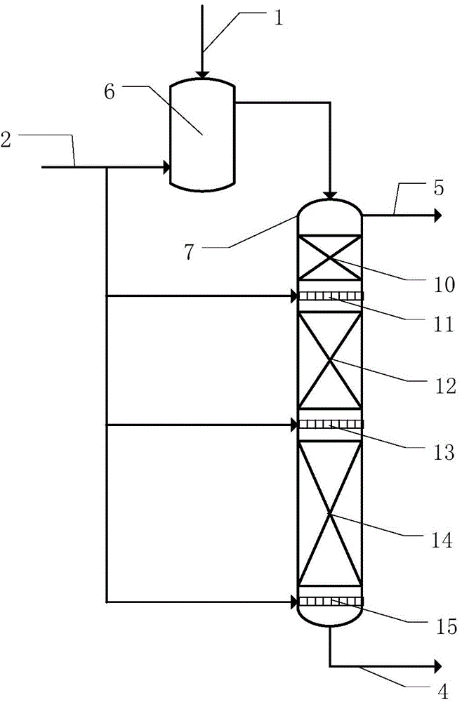
[0046] Such as figure 2 As shown, the reactor in the figure is a three-stage catalyst bed, such as the hydrocarbon raw material 1 of pre-hydrogenated naphtha (no other solvent is required as a diluent), in the gas-liquid mixer 6 at 80°C and 0.1MPa , fully mixed with fresh hydrogen 2 to realize the saturated dissolved state or unsaturated state (preferably saturated dissolved state) of hydrogen in the liquid phase hydrocarbon feedstock, and reach the system temperature and system pressure required for the reaction in the gas-liquid mixer 6, After entering the top of the reactor 7, the liquid-phase hydrocarbons preferably pass through the first-stage catalyst bed 10, the second-stage catalyst bed 12 and the third-stage catalyst bed 14 successively in the flow ...
Embodiment 2
[0049] Embodiment 2 is a change to the reactor form in Embodiment 1.
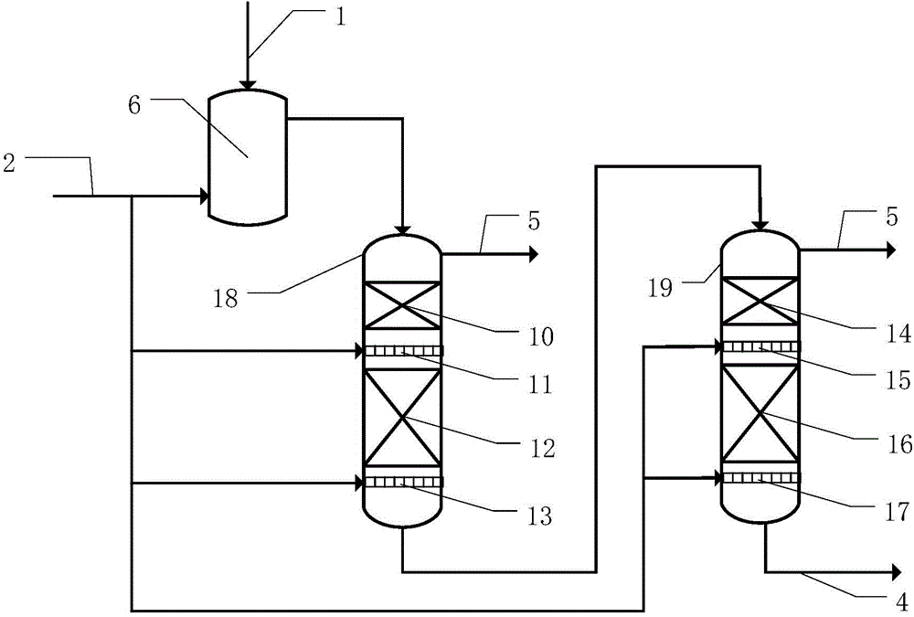
[0050] For the reaction of vacuum residue with high boiling point (diluent is VGO) under hydrogen-containing conditions, the operating conditions are 450 ° C and 16 MPa, and this process is applied, such as image 3 As shown, a first-stage reaction 18 and a second-stage reactor 19 are included. The two reactors are connected in series, and each reactor includes two stages of catalyst beds and a hydrogen distributor. This example is suitable for the situation where the physical and chemical indicators are harsh and the reaction depth is high, and it is also suitable for the situation where there are multiple catalysts and multiple target reactions.
Embodiment 3
[0052] For noble metal catalysts containing highly dispersed platinum metal, the process method is applied in the reaction process with the participation of hydrogen under the operating conditions of 80 ° C and 0.1 MPa.
[0053] Such as figure 2 As shown, the reactor in the figure is a three-stage catalyst bed, and the hydrocarbon raw materials are mixed oil of diesel oil, lubricating oil, and deasphalted oil (solvents are pentane and butane), and the gas-liquid mixer at 80°C and 0.1MPa In 6, fully mix with fresh hydrogen 2 to realize the saturated dissolved state or unsaturated state (preferably saturated dissolved state) of hydrogen in the liquid phase hydrocarbon raw material, and reach the system temperature and system required for the reaction in the gas-liquid mixer 6 pressure, and then enter the top of the reactor 7, the liquid-phase hydrocarbons preferably pass through the first-stage catalyst bed 10, the second-stage catalyst bed 12 and the third-stage catalyst bed 1...
PUM
 Abstract
Description
Claims
Application Information