
Porous hollow fiber membrane and method for manufacturing same

A manufacturing method and porous technology, applied in chemical instruments and methods, membranes, membrane technology, etc., can solve problems such as difficulty in taking into account mechanical strength, complex manufacturing methods of filtration membranes, molecular clogging, etc.

Inactive Publication Date: 2016-06-29
MITSUBISHI CHEM CORP
View PDF13 Cites 6 Cited by
  • Summary
  • Abstract
  • Description
  • Claims
  • Application Information

AI Technical Summary

Problems solved by technology

[0011] (6) The permeability of the treatment fluid is less likely to decrease over time
However, the filtration membranes formed of polyvinylidene fluoride hollow fiber membranes proposed so far have the following problems: in many cases, one or more of the properties of separation characteristics, filtration stability, and mechanical strength are insufficient. The manufacturing method of the filter membrane satisfying all requirements is complicated
However, this porous layer has a problem that large macrovoids exist inside the membrane structure due to its manufacturing method, and the separation characteristics are easily reduced due to damage to the outer surface of the membrane due to external factors.
However, when the dense layer is thickened like this, there is a problem that the dense layer may be clogged with extremely fine substances and / or soluble organic polymers, and the filtration stability may be reduced.
However, since the separation membrane of this technology has a high porosity and the pore diameter of the dense layer is approximately uniform, there still remains the problem that extremely minute substances and / or soluble organic polymers passing through the surface are easily It is clogged inside the dense layer. In addition, there are problems in the production method, that is, it must be substantially extended, so it is difficult to combine with the support body, and it is difficult to balance the mechanical strength.

Method used


Image

  • Porous hollow fiber membrane and method for manufacturing same
  • Porous hollow fiber membrane and method for manufacturing same
  • Porous hollow fiber membrane and method for manufacturing same

Examples


no. 2 approach

[0200] Another preferred embodiment of this embodiment will be described below.

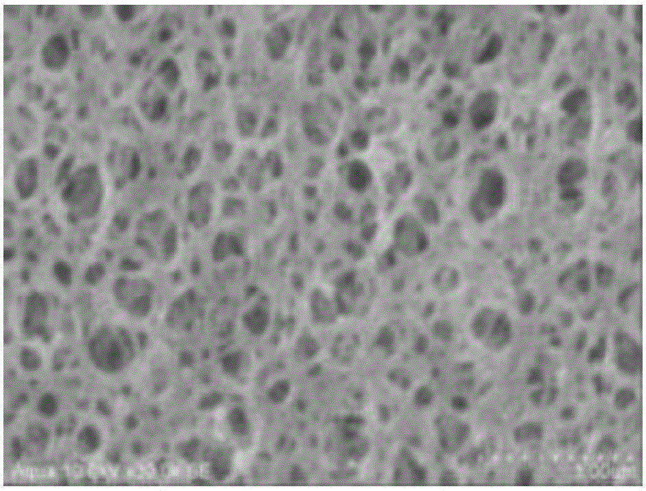
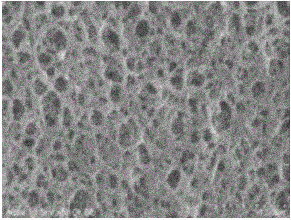
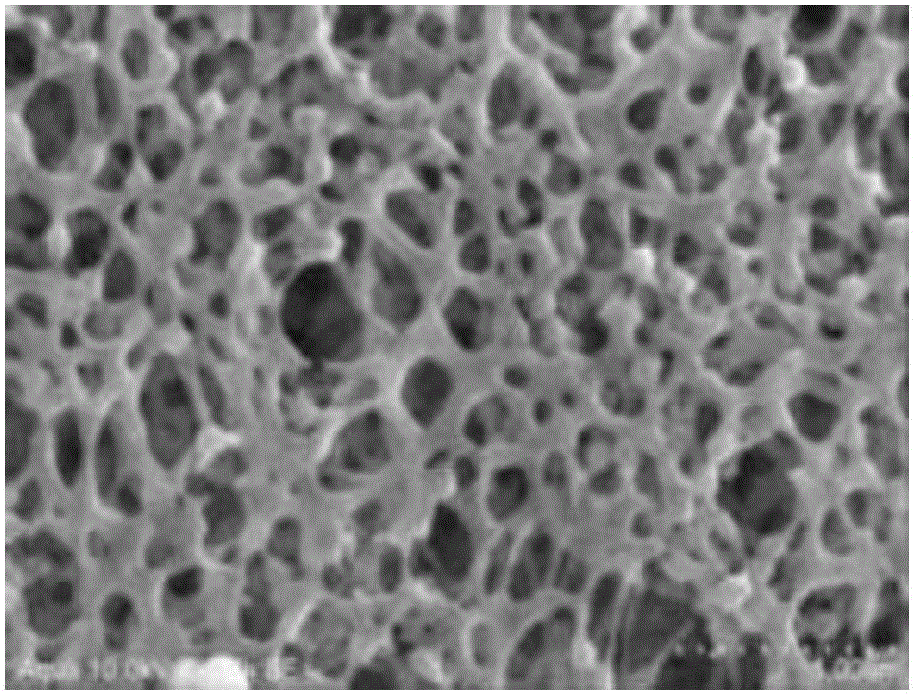
[0201] The hollow porous hollow fiber membrane of the present embodiment is a porous hollow fiber membrane in which, in the cross-sectional structure when cut in the thickness direction and observed, a layer from the surface to a depth of 1 μm (hereinafter referred to as a porous layer The ratio of the average pore size Ad of A.) to the size of the layer from a depth of 2 μm to 3 μm (hereinafter referred to as porous layer B.) Bd is 0.6 or less, preferably 1 / 2 or less (0.5 or less).

[0202] Here, the porous hollow fiber membrane of the present embodiment is characterized in that the membrane having the layer with the smallest pore diameter in the porous layer A forming the outer surface is substantially less than 1 μm, and extremely minute substances falling off the outer surface and / or Soluble organic polymers are not easy to clog inside the membrane.

[0203] Further, the porous hollow fiber ...

Embodiment 1

[0333] As the yarn for the hollow reinforcing support, polyester fiber (polyethylene terephthalate (PET), fineness: 84 dtex, filament number: 36, false twist (falsewisting) yarn) was used. As for the bobbins used in the production of the hollow reinforcement support, five bobbins wound with 5 kg of polyester fiber were prepared, and as a circular knitting machine (maru knitting machine), a desktop rope knitting machine (Takushang type knitting machine) was used (Sonoi Manufactured by Textile Machinery Co., Ltd., knitted fabric (meias) needle count: 12, needle size: 16 needle count (gauge, ゲージ), spindle diameter: 8mm). Nelson rolls (Nelson roll, Nelson Roll) were used as the rope supply device and the take-up device. As the heating die, a stainless steel die (outer diameter D: 5 mm, inner diameter d: 2.5 mm, length L: 300 mm) having a heating unit was used.

[0334] Five polyester fibers pulled out from the bobbin were combined into one fiber (total fineness; 420 dtex), and ci...

Embodiment 2

[0347] As the first and the second film-forming resin solutions, polyvinylidene fluoride (manufactured by Arkema, trade name Kynar761A) 19% by mass and polyvinylpyrrolidone (manufactured by Nippon Shokubai Co., Ltd., trade name K-80) mass A film-forming resin solution obtained by dissolving 12% in 69% by mass of N,N-dimethylacetamide while stirring. As a coagulation solution, 20% by mass of N,N-dimethylacetamide was used as a non-solvent A porous hollow fiber membrane was obtained in the same manner as in Example 1 except that pure water as a component was a coagulation solution having a composition of 80% by mass.

[0348] The viscosity of this film-forming resin solution at 40° C. was 250,000 mP·s.

[0349] Moreover, the average pore diameter of each layer was calculated similarly to Example 1 about the obtained porous hollow fiber membrane. The results are shown in Table 1.


PUM

PropertyMeasurementUnit
Average pore sizeaaaaaaaaaa

Abstract

Provided is a porous hollow fiber membrane and a method for manufacturing same, the porous hollow fiber membrane being able to be used suitably in devices for processing various water-based fluids for use in applications such as water purification, drinking-water processing, and seawater clarification; having excellent fractionation characteristics and permeability with minimal decrease in performance over time; having excellent recovery in membrane separation characteristics by washing: and having excellent separation characteristics, filtration stability, and mechanical strength. The present invention is a porous hollow fiber membrane having a porous layer made of a thermoplastic resin in at least an outer surface and the vicinity thereof, the average pore diameter (Ad) at a depth of 1 [mu]m from the surface as seen in cross-section being no more than 0.6 of the average pore diameter (Bd) from a depth of 2 to 3 [mu]m, and a method for manufacturing said membrane.

Description

technical field [0001] The present invention relates to a porous hollow fiber membrane excellent in fouling resistance mainly used for removing bacteria, viruses, SS components, etc. in water. Specifically, it relates to a porous hollow fiber membrane having long-term stable membrane performance and excellent recovery of membrane performance by washing. The present invention also relates to a porous hollow fiber membrane suitable for water treatment such as water purification treatment, which can be used as a precision filtration membrane or an ultrafiltration membrane, and a method for manufacturing the same. [0002] This application claims the priority of Japanese Patent Application No. 2013-193213 filed in Japan on September 18, 2013, and Japanese Patent Application No. 2013-193214 filed in Japan on September 18, 2013, and the contents thereof are incorporated herein. Background technique [0003] Sand filtration and the combined use of coagulation sedimentation and san...

Claims


Application Information

Patent Timeline
IPC IPC(8): B01D69/08B01D69/02B01D69/10B01D69/12
CPCB01D69/02B01D69/08B01D69/10B01D2325/021B01D2325/022B01D2325/40B01D69/1071B01D2325/0231B01D2325/0212
Inventor 寺町正史冈真理子福场芳则隅敏则广本泰夫藤木浩之溝越祐吾
Owner MITSUBISHI CHEM CORP
Learn More