On-chip integrated polarization beam splitter and polarization beam splitting method thereof
A polarization beam splitter and integrated technology, applied in the field of integrated optics, can solve the problems of large waveguide size, low refractive index, and low optical signal mode field limitation, and achieve large working bandwidth, large device manufacturing tolerance, and compact structure. Effect
- Summary
- Abstract
- Description
- Claims
- Application Information
AI Technical Summary
Problems solved by technology
Method used
Image
Examples
Embodiment 1
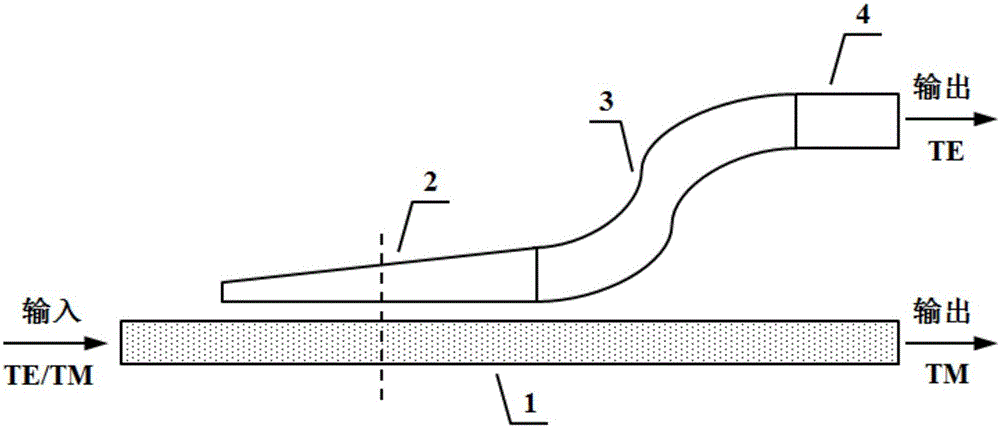
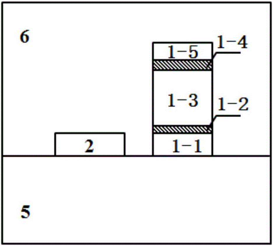
[0033] Embodiment 1: as Figure 1 to Figure 2 Shown is the structural diagram of the first embodiment of the present invention, and it comprises:
[0034]The substrate 5 is provided with a hybrid plasmonic waveguide 1, a taper-type coupling waveguide, an S-curve waveguide 3, and an output silicon waveguide 4 of the same thickness; a taper-type coupling waveguide, an S-curve waveguide 3, and an output silicon waveguide 4 in sequence In series and located on the same side of the hybrid plasmonic waveguide 1, the taper-type coupling waveguide and the hybrid plasmonic waveguide 1 are arranged in parallel; the hybrid plasmonic waveguide 1 is divided into metal covering layers 1-5, upper silicon dioxide layers 1-4, nitrogen Silicone waveguide layer 1-3, lower silicon dioxide layer 1-2 and silicon waveguide layer 1-1; coupling waveguide 2, S-curve waveguide 3 and output silicon waveguide 4 have the same thickness as silicon waveguide layer 1-1 ; The coupling waveguide 2 is a silicon...
Embodiment 2
[0039] Example 2: Figure 8 As the second embodiment of the present invention, an improved multimode interference coupler is used instead of a taper type directional coupler to couple the TE mode out. The multimode interference coupler is a rectangular waveguide. In order to reduce the reflection loss of the multimode interference coupler, we truncate the corner away from the hybrid plasmonic waveguide 1 among the two corners of the input end of the multimode interference coupler, which can effectively reduce the input and The influence of the partial reflection loss caused by the structural size mismatch between the output waveguide and the multimode interference coupler on the transmission performance. By optimizing the width and longitudinal transmission length of the multimode interference coupler, two high-performance linearly polarized modes, TE and TM, can be obtained at the output.
Embodiment 3
[0040] Example 3: Figure 9 The third embodiment of the present invention includes: a substrate 5, a hybrid plasmon waveguide 1 is arranged on the substrate 5, and a first coupling waveguide 2-1 and a second coupling waveguide 2-1 are respectively arranged on both sides of the hybrid plasmon waveguide 1. 2. The distance between the first coupling waveguide 2-1 and the second coupling waveguide 2-2 is equal to the hybrid plasmonic waveguide 1; the output end of the first coupling waveguide 2-1 is connected to the first output end through the first S-bend waveguide 3-1 The silicon waveguide 4-1 is connected; the output end of the second coupling waveguide 2-2 is connected with the second output silicon waveguide 4-2 through the second S-bend waveguide 3-2; the hybrid plasmonic waveguide 1 is divided into metal covering from top to bottom layer 1-5, upper silicon dioxide layer 1-4, silicon nitride waveguide layer 1-3, lower silicon dioxide layer 1-2 and silicon waveguide layer 1-...
PUM
| Property | Measurement | Unit |
|---|---|---|
| Thickness | aaaaa | aaaaa |
| Width | aaaaa | aaaaa |
| Width | aaaaa | aaaaa |
Abstract
Description
Claims
Application Information
 - R&D
- Intellectual Property
- Life Sciences
- Materials
- Tech Scout
- Unparalleled Data Quality
- Higher Quality Content
- 60% Fewer Hallucinations
Browse by: Latest US Patents, China's latest patents, Technical Efficacy Thesaurus, Application Domain, Technology Topic, Popular Technical Reports.
© 2025 PatSnap. All rights reserved.Legal|Privacy policy|Modern Slavery Act Transparency Statement|Sitemap|About US| Contact US: help@patsnap.com


