Air separation method utilizing liquefied natural gas cold energy to produce high pressure oxygen rich gas

A technology for liquefied natural gas and oxygen-enriched gas, which is applied in the direction of cold treatment separation, liquefaction, refrigeration and liquefaction, etc., can solve the problems of high production cost of liquid oxygen, high energy consumption of oxygen production, limited market scale, etc., to save equipment investment costs, High safety performance and low power consumption

Active Publication Date: 2016-07-20
JINAN UNIVERSITY
View PDF8 Cites 15 Cited by
  • Summary
  • Abstract
  • Description
  • Claims
  • Application Information

AI Technical Summary

Problems solved by technology

[0007] The above-mentioned existing patented method for air separation utilizing LNG cold energy all adopts a double-tower flow process to produce high-purity all-liquid air separation products, and there are following disadvantages in the use process: (1) because the transportation cost of liquid products is higher, The economic delivery radius of liquid air separation plant products is generally within 300km, and the market scale is limited; (2) the production cost of liquid oxygen is much higher than that of gas products, and it cannot be directly used in oxygen-enriched combustion plants; (3) the largest air separation plant The energy consumption comes from the air compressor, and most of the cryogenic air separation plants currently use a double-tower process of thermal integration of the high-pressure tower (lower tower) and the low-pressure tower (upper tower) to produce oxygen. Compressed to a high pressure (about 0.6MPa) to facilitate separation into the high-pressure tower, due to the high energy consumption of oxygen production, it is not suitable for capturing CO in oxygen-enriched combustion 2 used in the device

Method used


Image

  • Air separation method utilizing liquefied natural gas cold energy to produce high pressure oxygen rich gas
  • Air separation method utilizing liquefied natural gas cold energy to produce high pressure oxygen rich gas

Examples


Embodiment 1

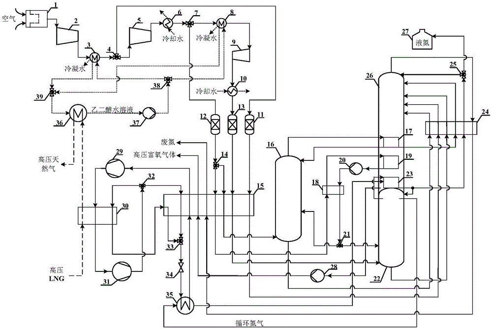
[0053] Such as figure 1 As shown, a kind of air separation method utilizing the cold energy of liquefied natural gas to produce high-pressure oxygen-enriched gas comprises the following steps and process conditions:

[0054] The molar composition of liquefied natural gas (LNG) at the receiving station is: methane 88.78%, ethane 7.54%, propane 2.59%, isobutane 0.45%, butane 0.56%, nitrogen 0.08%; the pressure of LNG entering the air separation unit is 10MPa, The temperature is about -150°C. The molar composition of the air raw material is: nitrogen 77.31%, oxygen 20.73%, argon 0.92%, CO 2 0.04%, water 1.02%; air pressure 0.101MPa, temperature 15°C. The isentropic efficiency of all compressors is 0.82 and the mechanical efficiency is 0.97; the isentropic efficiency of all pumps (including water pumps, liquid oxygen pumps and liquid air pumps) is 0.75 and the mechanical efficiency is 0.97.

[0055] Specific steps are as follows:

[0056] (1) Air compression and purification ...


PUM


Abstract

The invention belongs to the technical field of liquefied natural gas cold energy utilization, and particularly relates to an air separation method utilizing liquefied natural gas cold energy to produce a high pressure oxygen rich gas. The method specifically comprises the steps of (1) air compression and purification; (2) air liquefaction; (3) air rectification; and (4) LNG cold energy utilization. According to the air separation method, on one hand, a medium pressure tower and a medium pressure air condenser are additionally arranged for performing heat integration with a low pressure tower on the basis of a conventional double-tower air separation process, so that a part of raw air can be separated after being compressed to medium pressure, and the power consumption of an air compressor is greatly reduced; and circulating nitrogen is adopted as an intermediate medium, and the liquefied natural gas cold energy is utilized to condensate nitrogen at the tower top of a high pressure tower to provide cold energy for the air separation process, so that through utilizing the method, a quite high oxygen extraction rate is achieved, the liquefied natural gas is prevented from leaking and entering an air rectification unit, and the safety performance of a system is high.

Description

technical field [0001] The invention belongs to the technical field of liquefied natural gas cold energy utilization, in particular to an air separation method for producing high-pressure oxygen-enriched gas by using liquefied natural gas cold energy. Background technique [0002] In order to cope with climate change, countries around the world have been vigorously developing CO 2 Capture and storage (CCS) technology, among which oxyfuel combustion capture technology is considered to be one of the CCS technologies most likely to be promoted and commercialized on a large scale. Large-scale oxygen-enriched combustion capture devices need to consume a large amount of oxygen-enriched gas with a molar concentration lower than 97%. For example, an oxygen-enriched combustion power plant needs tens of thousands of tons of high-pressure oxygen-enriched oxygen every day. The energy consumption of oxygen production is huge, which can reduce the power generation efficiency of the power ...

Claims


Application Information

Patent Timeline
Patent Type & Authority Applications(China)
IPC IPC(8): F25J3/04
CPCF25J3/04448F25J3/04018F25J3/0406F25J3/0409F25J3/04169F25J3/04224F25J3/04272F25J2200/54F25J2205/62F25J2210/62F25J2230/04F25J2235/02F25J2245/40F25J2270/12F25J2270/42F25J2270/904F25J3/04024F25J3/04187F25J3/04266F25J3/04412
Inventor 熊永强罗鹏
Owner JINAN UNIVERSITY
Why Eureka
Try Eureka