A confocal and confocal alignment micro-assembly system and calibration method

A micro-assembly and co-imaging technology, which is applied in the field of micro-assembly and microscopic visual inspection, can solve the problems that the precise positioning requirements cannot be met in occasions, and the accuracy of part alignment detection is difficult to reach the sub-micron level, etc. The method is simple and easy to achieve , Improving the assembly accuracy and improving the effect of detection accuracy

Active Publication Date: 2018-10-16
BEIJING INSTITUTE OF TECHNOLOGYGY
View PDF4 Cites 0 Cited by
  • Summary
  • Abstract
  • Description
  • Claims
  • Application Information

AI Technical Summary

Problems solved by technology

[0003] Due to the limitation of the optical diffraction limit, the resolution of the traditional microscopic vision imaging system is an order of magnitude with the illumination wavelength, and the alignment detection accuracy of parts is difficult to reach the sub-micron level
Moreover, due to the limitation of the limited depth of focus, it cannot meet the requirements for occasions that require precise positioning in the depth direction.

Method used


Image

  • A confocal and confocal alignment micro-assembly system and calibration method
  • A confocal and confocal alignment micro-assembly system and calibration method
  • A confocal and confocal alignment micro-assembly system and calibration method

Examples


Embodiment 1

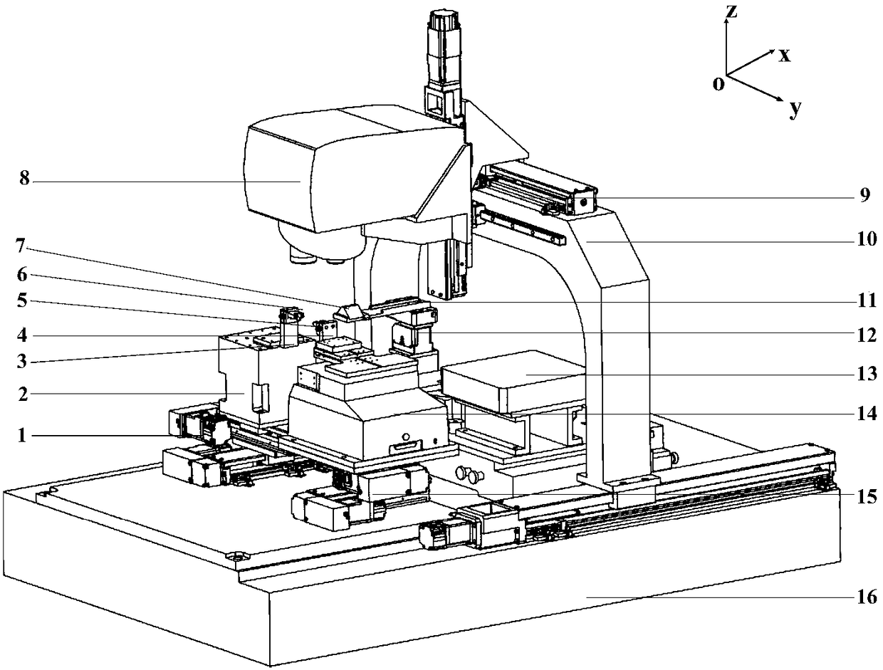
[0052] figure 1 It is a three-dimensional structure diagram of a confocal co-image alignment micro-assembly system of the present invention, and oxyz is the coordinate system of the system. Including target part two-dimensional displacement stage 1, target part lift table 2, target part holder 3, base part holder 4, base part 5, target part 6, trapezoidal prism 7, laser confocal microscope 8, grating ruler 9 , Gantry mechanism 10 , prism clamping mechanism 11 , prism posture adjustment mechanism 12 , detection table 13 , six-degree-of-freedom PI parallel micro-motion platform 14 , base part two-dimensional displacement table 15 , marble table 16 . The target part holder 3 is used to hold the target part 6, and below it is the target stage composed of the target part two-dimensional displacement stage 1 and the target part lifting table 2, which can realize the target part 6 along the x, y and z three directions. Linear displacement in one direction. The base part holder 4 is...

Embodiment 2

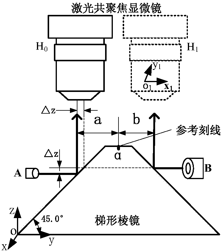
[0055] figure 2 It is the assembly principle diagram of a confocal confocal alignment micro-assembly system in the present invention and this embodiment; figure 2 As can be seen from the above, oxyz is the coordinate system of the system, and o1x1y1 is the image coordinate system of the system;

[0056] Before the system is assembled, the target part A and the base part B need to be installed on the target part holder and the base part holder respectively. After adjustment, there is a positional deviation between A and B in the x and z directions; the system assembly steps, details as follows:

[0057] First, move the laser confocal microscope to the H0 position to obtain the end face image of part A, so that the center line of the end face image coincides with the y1 axis of the confocal microscope image coordinate system;

[0058] Then, move the laser confocal microscope to the right above the reference line α, adjust the lens to obtain a clear image of the reference lin...

Embodiment 3

[0062] In this embodiment, a special trapezoidal prism is used. The two inclined surfaces of the trapezoidal prism are coated with a high-reflectivity aluminum film and a magnesium fluoride protective film. The reflectivity of the aluminum film for laser light with a wavelength of 400-700 nm is above 90%; the prism material is BK7; the surface accuracy is 1 / 4λ; the partial enlarged image of the upper surface pattern of the trapezoidal prism is shown in the figure image 3 As shown in the figure, it can be seen that there are reference cross scribe lines and square pattern scribe lines on the upper surface of the trapezoidal prism, the diagonal length of the square pattern is 0.5mm, and the line width of the reference cross scribe line and the square pattern are both 5 μm;

[0063] Figure 4 This is a flow chart of the present invention and a method for confocal alignment micro-assembly calibration in this embodiment. Depend on Figure 4 It can be seen from the above that the...


PUM


Abstract

The invention relates to a confocal common-imaging alignment micro assembling system and a calibration method, particularly to a confocal common-imaging alignment micro assembling system (short for a system) and a confocal common-imaging alignment micro assembling calibration method (short for a method). The system is composed of a laser confocal microscope, a portal frame mechanism, a trapezoid prism and a clamping mechanism thereof, a prism pose adjusting mechanism, a basic part and a clamping device thereof, a target part and a clamping device thereof, a substrate and a target objective table. In addition, the method includes: (1), the post of the trapezoid prism is adjusted and an angular deviation is eliminated; (2), laminating, alignment, and fixation of two calibration plates are completed and then the constraint of the two calibration pates is eliminated; (3), the two calibration plates are separated in a reverse direction and then the laser confocal microscope is moved right below the trapezoid prism; and (4), central coordinates of the two calibration plates and the trapezoid prism are measured by using the laser confocal microscope and a relative position error of the two calibration plates on the image plane of the laser confocal microscope is calculated. According to the invention, the system and the method are easy to implement; and the alignment and assembling precision of micro assembling is improved.

Description

technical field [0001] The invention relates to a confocal co-image alignment micro-assembly system and a calibration method, belonging to the technical fields of micro-assembly and microscopic visual inspection. Background technique [0002] Guidance and guidance instruments in the aviation field, fuze components in intelligent ammunition, and target components in inertial confinement nuclear fusion systems are all urgently needed core equipment for my country's major scientific and technological research, and their assembly level seriously restricts the development of a new generation of high-end manufacturing. . In order to ensure the accuracy and performance of micro-miniature systems, the assembly gap of such instruments or components often needs to be strictly controlled at the micron level, and the alignment detection accuracy needs to reach the sub-micron level. [0003] Due to the limitation of optical diffraction limit, the resolution of traditional microscope visi...

Claims


Application Information

Patent Timeline
Patent Type & Authority Patents(China)
IPC IPC(8): G01B11/00
CPCG01B11/00
Inventor 叶鑫张之敬李扬蔡绍鹏周登宇刘玉红
Owner BEIJING INSTITUTE OF TECHNOLOGYGY
Why Eureka
Try Eureka