Dehumidifier

A dehumidifier and runner technology, applied in the field of low-temperature regenerative low dew point energy-saving dehumidifiers, can solve the problems of high cost of dehumidifiers and high energy consumption of dehumidifiers, and achieve the goal of alleviating the shortage of electricity, realizing energy supply and reducing emissions Effect

Inactive Publication Date: 2016-08-24
SEIBU GIKEN CO LTD
View PDF5 Cites 10 Cited by
  • Summary
  • Abstract
  • Description
  • Claims
  • Application Information

AI Technical Summary

Problems solved by technology

However, since three-stage dehumidification rotors are required, of course three regenerative heaters are also required
Therefo...

Method used


Image

  • Dehumidifier
  • Dehumidifier
  • Dehumidifier

Examples


Embodiment 1

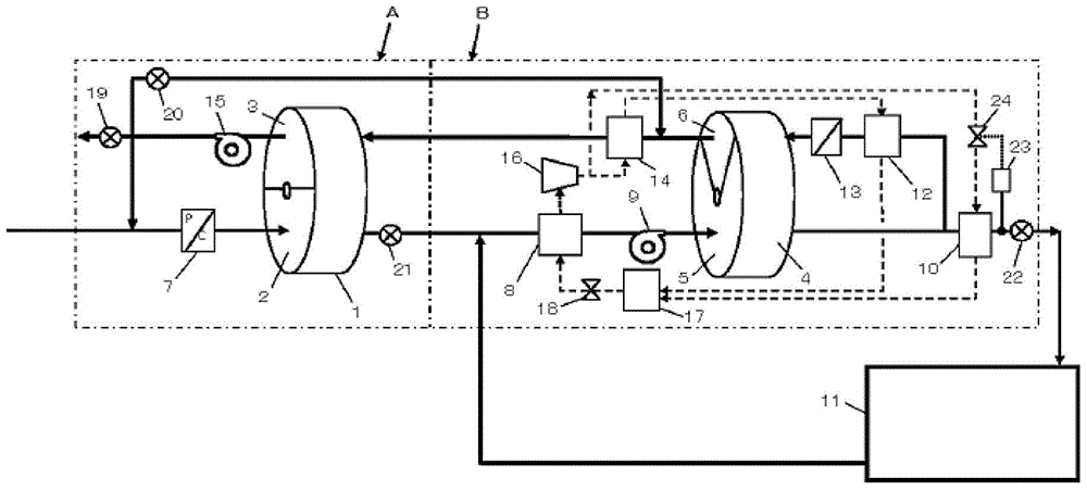
[0046] figure 1 It is a schematic flow diagram of one of the embodiments of the present invention. The number 1 in the figure is the first-stage dehumidification rotor, which is divided into two areas: treatment area 2 and regeneration area 3, 4 is the second-stage dehumidification rotor, and the second-stage dehumidification rotor is also divided It is divided into two areas: treatment area 5 and regeneration area 6.

[0047] 7 is the first cooler, which is used to cool the outdoor fresh air OA, through the first cooler, the outdoor fresh air is cooled to below its dew point temperature, so that the water vapor contained in it is condensed into condensed water and discharged to The dehumidifier is installed outside, so as to achieve the pretreatment purpose of cooling and dehumidifying the outdoor fresh air. The air cooled and dehumidified by the first cooler is sent to the treatment area 2 of the first-stage dehumidification wheel 1 by the suction force of the treatment fa...

Embodiment 2

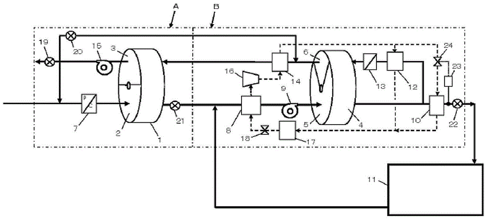
[0061] figure 2 It is the figure of Example 2 of this invention. Due to the process of dehumidifier installation and figure 1 The ones shown are basically the same, and the descriptions of the repeated parts are omitted. exist figure 1 In the embodiment, the condenser serving as the fourth heater 14 is connected in series with the refrigerant circulating in the condenser serving as the second heater 12, and then formed with the refrigerant circulating in the condenser serving as the first heater 10. Parallel state. while in figure 2 In the shown embodiment, the flow conditions of the refrigerant in the condenser as the first heater 10 and the refrigerant in the condenser as the second heater 12 are in parallel state, and then with the condenser as the fourth heater 14 The refrigerant flow in the system forms a series state. If it is not possible to use the dehumidifier due to the location where the dehumidifier is installed figure 1 The implementation shown can be use...

Embodiment 3

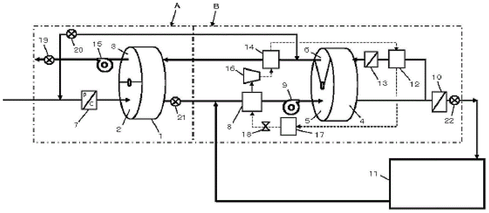
[0068] image 3 It is a schematic flow chart of Embodiment 3 of the present invention. The first-stage desiccant wheel 1 is divided into two areas: a treatment area 2 and a regeneration area 3 , and the second-stage dehumidification wheel 4 is also divided into two areas: a treatment area 5 and a regeneration area 6 .

[0069] Cool the outdoor fresh air OA to below its dew point temperature through the first cooler 7, so that the water vapor contained in it is condensed into condensed water and discharged to the outside of the dehumidifier device, so as to achieve the pretreatment of cooling and dehumidifying the outdoor fresh air Purpose. The air cooled and dehumidified by the first cooler 7 is sent to the treatment area 2 of the first-stage dehumidification wheel 1 by the suction force of the treatment fan 9, and the air after passing through the treatment area 2 is combined with the return air returned from the drying room After the air RA is mixed, it enters the second c...


PUM


Abstract

The invention provides an adsorption type dehumidifier. The adsorption type humidifier employs two dehumidification rotors; ambient air passes a first cooler, a processing zone of a first dehumidification rotor, a second cooler, a processing zone of a second dehumidification rotor, and a first heater in order, the air is adjusted to a required temperature and sent to a drying room. Return air from the drying room and air which passes the processing zone of the first dehumidification rotor are mixed, and the mixed air is sent to a regeneration zone. One part of the air is sent to a regeneration zone of the second dehumidification rotor through a second heater and a third heater. The air passes a fourth heater and is sent to the regeneration zone of the first dehumidification rotor, and the air which passes the regeneration zone of the first dehumidification rotor is branched into two parts, wherein one part turns to an outlet of the regeneration zone of the second dehumidification rotor and is mixed with air from the outlet, and the other part is sent to an inlet of the first cooler and mixed with ambient air, and the mixed air enters a part of the first cooler.

Description

technical field [0001] The invention belongs to an adsorption rotary dehumidifier, in particular to a low-temperature regenerating low dew point energy-saving dehumidifier capable of using the exhaust heat of a heat pump as a regeneration heat source. Background technique [0002] In recent years, with the increase in demand for lithium-ion batteries and lithium-ion capacitors, their production capacity has also been expanding. Lithium metal, one of the raw materials of lithium-ion batteries, easily reacts with moisture in the air. This chemical reaction not only reduces the quality of lithium-ion batteries, but also poses a potential safety hazard. Therefore, lithium-ion battery production lines generally need to be maintained in a dry state with a low dew point. The methods to maintain the production line in a dry state include: using nitrogen replacement method; using silica gel and other adsorption runners to absorb and remove moisture in the air to prepare dry air. ...

Claims


Application Information

Patent Timeline
IPC IPC(8): F24F1/00F24F12/00F24F13/30F26B21/00B01D53/26
CPCB01D53/265B01D2257/80F24F1/00F24F12/001F24F13/30F24F2203/10F26B21/001Y02P70/10
Inventor 金伟力
Owner SEIBU GIKEN CO LTD
Why Eureka
Try Eureka