Flue gas waste heat recovery and flue gas processing system based on organic Rankine cycle

A flue gas treatment system, Rankine cycle technology, applied in mechanical equipment, steam engine installations, climate sustainability, etc., can solve the problem of small demand for hot and cold users, increased complexity of steam turbine systems, and small heat exchange temperature difference and other issues, to achieve the effect of improving efficiency and energy utilization, being conducive to environmental protection, and promoting energy conservation and emission reduction.

Active Publication Date: 2016-08-31
SOUTHEAST UNIV
View PDF5 Cites 16 Cited by
  • Summary
  • Abstract
  • Description
  • Claims
  • Application Information

AI Technical Summary

Problems solved by technology

Taking the waste heat of flue gas in a power station as an example, the general exhaust gas temperature of the power station is 120°C to 140°C, and the temperature required for flue gas desulfurization is 90°C, so it is necessary to lower the temperature of the flue gas. The cooling method generally adopted by the power station is A low-temperature economizer is arranged in the tail flue of the boiler, and the feed water is heated by the flue gas. In this way, the heat exchange temperature difference is small, and a large water flow rate is required to lower the temperature of the flue gas, and the complexity of the steam turbine system increases. The steam turbine needs Redesign, it is difficult to adjust and control operation when the steam turbine changes working conditions
Other types of flue gas waste heat application technologies mainly focus on refrigeration and heating, but this technology lacks heat users, or heat users have little, discontinuous or fluctuating demand for cold and heat, while industrial flue gas is It has always existed and the amount remains unchanged, so the use of waste heat refrigeration and heating technology is a discontinuous process, resulting in the waste heat of the flue gas not being utilized or the utilization rate is not high

Method used


Image

  • Flue gas waste heat recovery and flue gas processing system based on organic Rankine cycle
  • Flue gas waste heat recovery and flue gas processing system based on organic Rankine cycle
  • Flue gas waste heat recovery and flue gas processing system based on organic Rankine cycle

Examples


Embodiment

[0026] The present invention will be described in detail below with reference to the accompanying drawings and specific embodiments. In this embodiment, calculation analysis is performed in conjunction with data, but the protection scope of the present invention is not limited to the following embodiments.

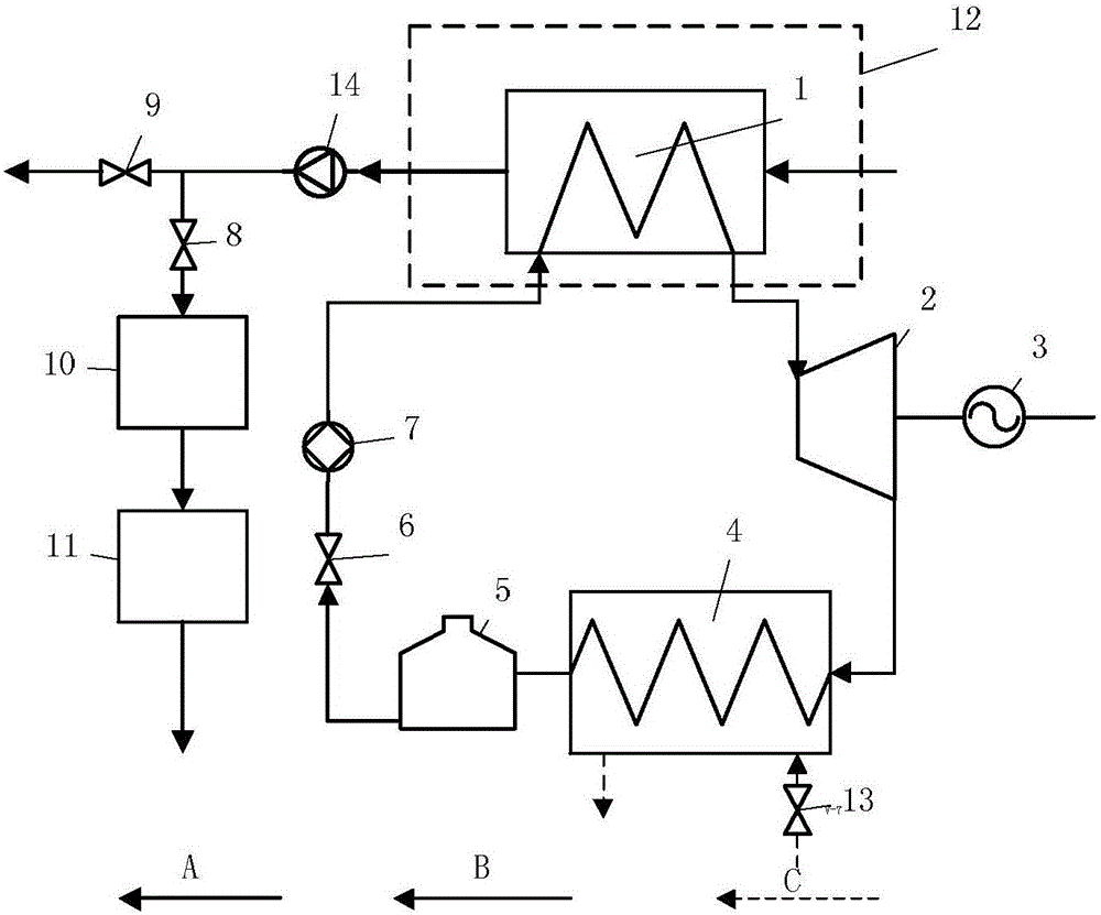
[0027] The flue gas waste heat recovery and treatment system based on the organic Rankine cycle of the present embodiment is as follows: figure 1 As shown in the figure, the system is composed as follows: the evaporator 1 is installed in the flue 12 at the tail of the furnace, so that the flue gas at the tail of the boiler passes through the evaporator 1, the dust collector 10 and the harmful gas removal device 11 successively for heat release, dust removal and absorption of harmful gases. After that, it is discharged into the atmosphere; the evaporator 1, the expander 2, the condenser 4, the liquid storage tank 5, the organic working fluid control valve 6 and the working f...


PUM


Abstract

The invention relates to a flue gas waste heat recovery and flue gas processing system based on organic Rankine cycle. The system includes an organic Rankine cycle power generation system and a flue gas processor system. The organic Rankine cycle power generation system includes an evaporator, an expansion machine, a power generator, a condenser, a liquid storage bin, a working medium pump and an organic working medium flow control valve. The flue gas processor system includes a dust remover and a harmful gas absorbing device. According to the invention industrial after heat power generation system and the flue gas processor are combined. The industrial after heat power generation system recovers low grade after heat in industry and outputs electric energy, so that the industrial after heat utilization rate and energy utilization rate are improved. The flue gas processor processes industrial flue gas, so that pollutant discharge is reduced. The system realizes energy conservation and emission reduction and improves energy utilization rate.

Description

technical field [0001] The invention belongs to the field of medium and low temperature waste heat utilization, in particular to a flue gas waste heat recovery and flue gas treatment system based on organic Rankine cycle. Background technique [0002] The energy issue is the primary issue of social and economic development. In recent years, with the rapid economic development, my country's demand for energy has shown a trend of rapid growth. At present, my country's energy utilization still has the main problems of low utilization efficiency, poor economic benefits, and high pressure on the ecological environment, which greatly restricts the development of my country's economy. [0003] Energy conservation and emission reduction, reduction of energy consumption, and improvement of comprehensive utilization of energy are important contents of energy development strategic planning, and are the fundamental way to solve my country's energy problems, and are in a priority positi...

Claims


Application Information

Patent Timeline
Patent Type & Authority Applications(China)
IPC IPC(8): F01K27/00F01K25/10B01D53/78B01D53/60B01D53/62
CPCB01D53/60B01D53/62B01D53/78B01D2251/306B01D2251/604F01K25/10F01K27/00Y02A50/20Y02P80/15
Inventor 胥建群张方陈飞翔
Owner SOUTHEAST UNIV
Why Eureka
Try Eureka