Flexible heat preservation assembly

A flexible and component technology, which is applied in the thermal insulation structure, flexible thermal insulation components, and the thermal insulation field of special-shaped components, can solve the problems of heat loss, increase the air supply volume, and poor installation accuracy, so as to block heat conduction and convection and ensure the sealing effect , Improve the effect of construction efficiency

Active Publication Date: 2016-08-31
BEIJING HAORUISEN TRADE +1
View PDF7 Cites 17 Cited by
  • Summary
  • Abstract
  • Description
  • Claims
  • Application Information

AI Technical Summary

Problems solved by technology

Therefore, the insulation materials used in the package generally cannot be prefabricated in the factory, and need to be packaged manually on site, resulting in poor installation accuracy and high heat loss rate
This is especially true for traditional rigid insulation materials such as polyurethane, rock wool, and silicate. In addition to high thermal conductivity, high energy loss rate, and short life of the insulation layer, it is also difficult to disassemble and difficult to restore after disassembly, resulting in the failure of the insulation material. Reuse, and the problem of losing a lot of heat
[0004] Even if airgel materials are used to wrap flanges and valves, it is still difficult to fully fit the pipes and equipment due to the insulation material
There is air in the gap, and the heat will be lost through convection, so the heat loss is still relatively large
In addition, there are gaps when the insulation material is butted or sealed. Traditional methods, such as bonding, binding, and sealing with sealing strips, still have gaps in the sealing place, resulting in a large amount of heat loss.
[0005] Taking the steam pipeline as an example, using the original heat preservation technology, a lot of heat will be lost in the valves and other places, and the steam will often condense into water during the transportation process, resulting in the gas supply volume not meeting the needs of production and living
In order to achieve the designed outlet steam temperature and quantity, the air supply volume must be increased, thus causing energy waste and economic loss

Method used


Image

  • Flexible heat preservation assembly
  • Flexible heat preservation assembly
  • Flexible heat preservation assembly

Examples


Embodiment 1

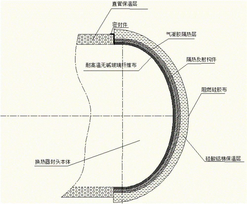
[0054] Figure 4a , 4b and Figure 5 An example of the application of the flexible thermal insulation component of the present invention to the head of a heat exchanger is given. Although the figure only shows an example of one layer of heat-insulating reflective member and two layers of heat-insulating layer, those skilled in the art know that the number of layers and positions of the heat-insulating reflective member and heat-insulating layer can be adjusted. The structure of the flexible thermal insulation component used for the heat exchange head is as follows from the inside to the outside: high temperature resistant alkali-free glass fiber cloth, heat insulation reflective member, airgel heat insulation layer, aluminum silicate cotton insulation layer, flame retardant silicone cloth ;Use flexible seals at the assembly's joints with straight pipe insulation or other structural joints.

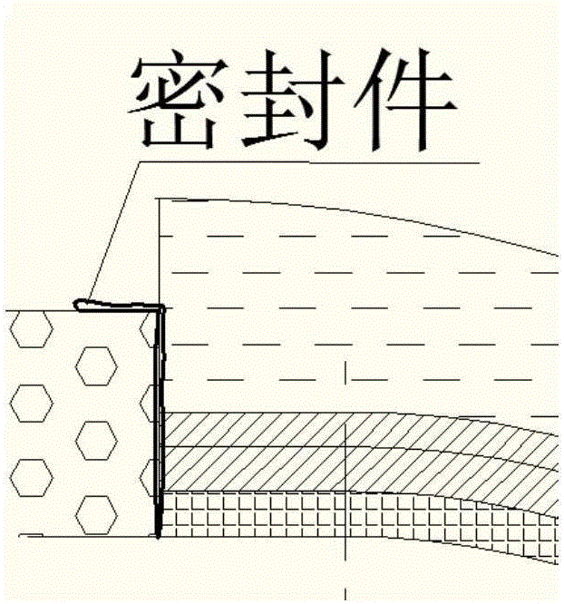
[0055] Figure 5 yes Figure 4a Enlarged view of the middle seal. Since the head...

Embodiment 2

[0058] Figure 6 A schematic diagram of the application of the flexible thermal insulation component of the present invention to a flange is given. Although the figure only shows an example of one layer of heat-insulating reflective member and two layers of heat-insulating layer, those skilled in the art know that the number of layers and positions of the heat-insulating reflective member and heat-insulating layer can be adjusted. The structure of the flexible thermal insulation component used for the flange is from the inside to the outside: high temperature resistant alkali-free glass fiber cloth, heat insulation reflective member, airgel heat insulation layer, aluminum silicate wool heat insulation layer, flame retardant silicone cloth; Flexible seals are used at the seams.

[0059] In order to facilitate installation, the flexible thermal insulation component can be divided into two parts, prefabricated in the factory or on site, and then directly sleeved on the flange, t...

Embodiment 3

[0061] Figure 7 A schematic diagram of the application of the flexible thermal insulation component of the present invention to a valve is given. Although the figure only shows an example of one layer of heat-insulating reflective member and two layers of heat-insulating layer, those skilled in the art know that the number of layers and positions of the heat-insulating reflective member and heat-insulating layer can be adjusted. The structure of the flexible thermal insulation component used for valves is as follows from inside to outside: high temperature resistant alkali-free glass fiber cloth, heat insulation reflective member, airgel heat insulation layer, aluminum silicate cotton heat insulation layer, flame retardant silicone cloth; Use flexible seals at seams.

[0062] In order to facilitate installation, the flexible thermal insulation component can be divided into two parts, prefabricated in the factory or on site, and a straight pipe and a hole through which the va...


PUM


Abstract

The invention relates to a flexible heat preservation assembly. The flexible heat preservation assembly is characterized in that the flexible heat preservation assembly comprises one or more layer of heat insulation reflecting component and heat insulation layers, wherein the heat insulation reflecting component comprises metal foil pieces and flexible heat insulation mats, and the flexible heat insulation mats are clamped between the metal foil pieces; and the number of the flexible heat insulation layers is more than one. The flexible heat preservation assembly is good in heat preservation performance, and heat emitted by high-temperature equipment can be effectively isolated; and in addition, the flexible heat preservation assembly is flexible in arrangement and economical, and the number of layers of the stacked structure can be set according to requirements.

Description

technical field [0001] The invention relates to a thermal insulation structure, which belongs to the technical field of thermal insulation, and specifically relates to a flexible thermal insulation component, which can be used for thermal insulation of pipelines and high-temperature equipment, and is especially suitable for thermal insulation of special-shaped components such as heads, valves, and flanges. . Background technique [0002] Existing thermal insulation technology uses polyurethane, rock wool, silicate and other thermal insulation materials to insulate high-temperature pipelines or high-temperature equipment. However, the existing thermal insulation materials have high thermal conductivity, high energy loss rate, and short life of the insulation layer. SiO 2 Due to its special nanopore size and skeleton particles, airgel is currently recognized as one of the solid materials with the lowest thermal conductivity. Because of its good chemical stability, acid and al...

Claims


Application Information

Patent Timeline
Patent Type & Authority Applications(China)
IPC IPC(8): F16L59/02F16L59/08F16L59/04
CPCF16L59/029F16L59/04F16L59/08
Inventor 刘洪涛邹军锋张天翔雷雨刘斌
Owner BEIJING HAORUISEN TRADE
Why Eureka
Try Eureka