Current loop control system based FPGA, and servo device

A technology of control system and current controller, which is applied in the direction of control system, vector control system, control electromechanical transmission device, etc. It can solve the problem of low control precision of servo control system, long execution time of current loop algorithm, and limited operation mode of current loop and other problems, to achieve the effects of shortening the execution time, improving the accuracy of steady speed and dynamic response, and good sine

Inactive Publication Date: 2016-09-07
SHANGHAI STEP ELECTRIC +1
View PDF4 Cites 18 Cited by
  • Summary
  • Abstract
  • Description
  • Claims
  • Application Information

AI Technical Summary

Problems solved by technology

[0005] The current loop of the existing servo control system is limited by the running mode of code serial execution, which makes the execution time of the current loop algorithm longer, resulting in a longer de...

Method used


Image

  • Current loop control system based FPGA, and servo device
  • Current loop control system based FPGA, and servo device
  • Current loop control system based FPGA, and servo device

Examples


Embodiment Construction

[0030] In order to make the object, technical solution and advantages of the present invention clearer, various embodiments of the present invention will be described in detail below in conjunction with the accompanying drawings. However, those of ordinary skill in the art can understand that, in each implementation manner of the present invention, many technical details are provided for readers to better understand the present application. However, even without these technical details and various changes and modifications based on the following implementation modes, the technical solution claimed in each claim of the present application can be realized.

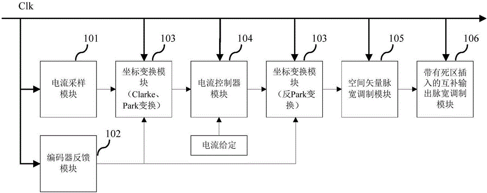
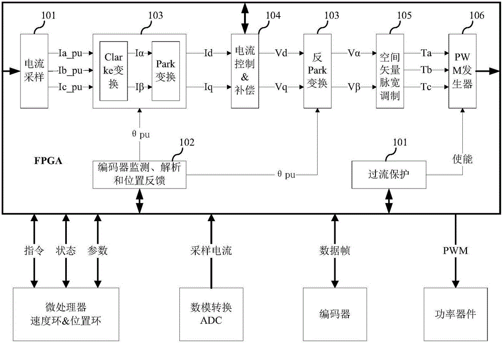
[0031] The first embodiment of the present invention relates to an FPGA-based current loop control system. The specific structure is as figure 1 shown. The system includes: a current sampling module 101, an encoder feedback module 102, a coordinate transformation module 103, a current controller module 104, a space vector ...


PUM


Abstract

The invention relates to the technical field of alternating current servo vector control, and discloses a current loop control system based on an FPGA, and a servo device. According to the system and the device, through adoption of current loop control based on an FPGA hardware logic parallel processing mode, a current given quantity and signals sent by a current sampling module are input into a current controller module for PID calculation and decoupling compensation processing, a voltage vector reference value under a rotating coordinate system is output; a voltage vector reference value under a static coordinate system is output according to a rotor angle value output by an encoder feedback module and the output voltage vector reference value under the rotating coordinate system; a space vector pulse width modulation module converts the voltage vector reference value under the static coordinate system into three-way effective duty cycles; a complementary output pulse width modulation module with dead zone insertion converts the three-way effective duty cycles into six-way pulse width modulation square signals after dead-time compensation. Through adoption of the system and the device, the current loop control time is reduced, and the current loop bandwidth is improved.

Description

technical field [0001] The invention relates to the technical field of AC servo vector control, in particular to an FPGA-based current loop control system and a servo device. Background technique [0002] With the rapid development of power electronics technology, microelectronics technology, and new motor control theory, AC servo drive technology has become one of the key technologies of modern electromechanical equipment. Servo control is usually a three-loop control system, which is the current loop, the speed loop, and the position loop from the inside to the outside. Among them, the current loop is the inner loop of the system, and the speed loop and position loop are the outer loops of the system. As a multi-loop control system, the performance of the outer loop depends on the performance of the inner loop. The current loop is the key to improve the control precision and response speed in the servo control system. In order to improve the dynamic and static performanc...

Claims


Application Information

Patent Timeline
IPC IPC(8): H02P21/22H02H7/08
CPCH02H7/08H02H7/0805H02H7/0844
Inventor 严彩忠丁信忠李虎修柳竹青周建坤
Owner SHANGHAI STEP ELECTRIC
Why Eureka
Try Eureka