Half-dry type flue gas desulfurization device and method

A desulfurization device and semi-dry technology, which is applied in the field of flue gas desulfurization equipment and semi-dry flue gas desulfurization device, can solve the problem of increasing sticking tower and dust bag clogging, increasing the work load of booster fan, and increasing desulfurization agent consumption, etc. problem, to achieve the effect of good effect, reduced workload and low desulfurization cost

Inactive Publication Date: 2016-09-28
HEBEI IRON AND STEEL
View PDF5 Cites 3 Cited by
  • Summary
  • Abstract
  • Description
  • Claims
  • Application Information

AI Technical Summary

Problems solved by technology

This semi-dry flue gas desulfurization device and method has the following disadvantages: since the lower part of the Venturi of the desulfurization tower is directly in contact with the atmosphere, part of the cold air drawn by the booster fan enters the desulfurization tower, which not only increases the workload of the booster fan, but also The humidity in the tower increases, the flue gas temperature decreases, and the probability of sticking to the tower and dust bag clogging during spraying increases. Therefore, the ambient temperature and flue gas temperature have a greater impact on desulfurization, and low ambient temperature or flue gas temperature will cause Increased desulfurization agent consumption and low desulfurization efficiency; when the flue gas flow rate at the inlet of the desulfurization tower is close to the suction capacity of the booster fan, positive pressure is likely to form in the flue at the inlet of the desulfurization system and the desulfurization tower, resulting in ash falling, which not only affects the desulfurization effect , and cause waste of desulfurization agent and environmental pollution

Method used


Image

  • Half-dry type flue gas desulfurization device and method

Examples


Embodiment Construction

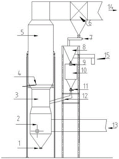
[0016] The device of the present invention consists of a desulfurization tower, a cloth bag filter 6, a screw feeder 7, a waste ash bin 8, a circulating ash bin 10, a circulating ash delivery pipe 12, a sulfur-containing waste gas inlet pipe 13, a desulfurization waste gas discharge pipe 14, and a desulfurization waste The ash discharge device 15 consists of a desulfurization tower including a flue gas chamber 2, a Venturi chamber 3, and a desulfurization tower reaction chamber 5, and a nozzle 4 is installed in the desulfurization reaction chamber.

[0017] The figure shows that a desulfurization tower dust discharge valve 2 is installed at the lower end of the flue gas chamber 3 at the bottom of the desulfurization tower, the flue gas chamber 2 at the bottom of the desulfurization tower is connected to the inlet pipe 13 for sulfur-containing waste gas, and the upper part of the flue gas chamber 2 is connected to the Venturi chamber 3 , the top of the Venturi chamber 3 is conne...


PUM


Abstract

A semi-dry flue gas desulfurization device and method, belonging to the technical field of flue gas desulfurization equipment and methods. The technical solution is: a desulfurization tower ash discharge valve is added at the bottom of the desulfurization tower. During the desulfurization process, the desulfurization tower ash discharge valve at the bottom of the desulfurization tower flue chamber is closed to prevent cold air from entering the desulfurization tower. The working load of the booster fan, and ensure the stability of humidity and flue gas temperature in the desulfurization tower, so the ambient temperature and flue gas temperature have no effect on desulfurization. Due to the stable humidity and flue gas temperature in the tower, it avoids the sticking of the tower and the clogging of the dust bag during spraying, and the desulfurization cost is low and the desulfurization efficiency is high. At the same time, the ash in the circulating ash bin of the present invention enters the Venturi chamber through the circulating ash conveying pipe. When the flue gas flow rate at the entrance of the desulfurization tower is large, part of the flue gas is sealed in the lower part of the Venturi chamber 3 by the ash discharge valve of the circulating ash bin. To support the returning ash, prevent falling, avoid environmental pollution, reduce production costs, and have significant economic and social benefits.

Description

technical field [0001] The invention relates to a semi-dry flue gas desulfurization device and method, and belongs to the technical field of flue gas desulfurization equipment and methods. Background technique [0002] As an important air pollutant, the concentration of sulfur dioxide must be controlled below 180mg / m³ in the waste gas emitted by production enterprises to the atmosphere. Therefore, flue gas desulfurization is an essential part of thermal power generation, sintering, and vanadium extraction. Commonly used flue gas desulfurization processes mainly include wet method (lime / limestone-gypsum method), semi-dry method (spray drying method), absorption regeneration method, calcium spraying-humidification activation method, etc. Compared with other desulfurization processes, the semi-dry flue gas desulfurization process has the advantages of simple internal structure of the desulfurization tower, no power components, small resistance loss, and low equipment maintenanc...

Claims


Application Information

Patent Timeline
Patent Type & Authority Applications(China)
IPC IPC(8): B01D46/02B01D53/50B01D53/80
CPCB01D46/023B01D53/50B01D53/80B01D2258/0283
Inventor 隋孝利钟闯王挽平田岩松李鹏赵建军
Owner HEBEI IRON AND STEEL
Why Eureka
Try Eureka